 LK Automation Limited
Brand:
MITSUBISHI
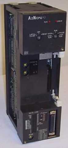
A2NCPUP21 | MITSUBISHI CPU unit A2NCPUP21
MITSUBISHI A2NCPUP21 Manual And Instructions
A2NCPUP21 datasheetPDF datasheet
A2NCPUP21 Common InstructionsProgramming Manual
A2NCPUP21 User's Manual
A2NCPUP21 HardwareUser's Manual
A2NCPUP21 Dedicated InstructionsProgramming Manual
A2NCPUP21 FundamentalsProgramming Manual
MITSUBISHI A2NCPUP21 Product information and technical parameters:
Brand: MITSUBISHI
Name: CPU unit
Model: A2NCPUP21
Input and output points: 512 points.
Input / output data points: 512 points.
Program capacity: 14K.
Basic command processing speed (LD command) s:1.0.
Optical data communication line.
User program storage capacity: it is a measure of how much the user application can store the number of indicators.
Usually in words or K words as units. 16 bit binary number is a word,
Every 1024 words are 1K words. PLC to store instructions and data in words.
General logical operation instructions each account for 1 words. Timer / counter,
Shift instruction accounted for 2 words. Data operation instructions for 2~4.
Integral type: the PLC components are installed together or a few pieces of printed circuit board,
And together with the power supply installed in the casing to form a single overall called the host or the basic unit, small, ultra small PLC using this structure.
Modular: PLC is the basic components of a separate module.
Medium and large PLC used this way. Easy maintenance.
...More relevant models >>>>
A2NCPUP21 datasheetPDF datasheet
A2NCPUP21 Common InstructionsProgramming Manual
A2NCPUP21 User's Manual
A2NCPUP21 HardwareUser's Manual
A2NCPUP21 Dedicated InstructionsProgramming Manual
A2NCPUP21 FundamentalsProgramming Manual
MITSUBISHI A2NCPUP21 Product information and technical parameters:
Brand: MITSUBISHI
Name: CPU unit
Model: A2NCPUP21
Input and output points: 512 points.
Input / output data points: 512 points.
Program capacity: 14K.
Basic command processing speed (LD command) s:1.0.
Optical data communication line.
User program storage capacity: it is a measure of how much the user application can store the number of indicators.
Usually in words or K words as units. 16 bit binary number is a word,
Every 1024 words are 1K words. PLC to store instructions and data in words.
General logical operation instructions each account for 1 words. Timer / counter,
Shift instruction accounted for 2 words. Data operation instructions for 2~4.
Integral type: the PLC components are installed together or a few pieces of printed circuit board,
And together with the power supply installed in the casing to form a single overall called the host or the basic unit, small, ultra small PLC using this structure.
Modular: PLC is the basic components of a separate module.
Medium and large PLC used this way. Easy maintenance.
MITSUBISHI PLC hardware implementation
Hardware implementation is mainly for the control cabinet and other hardware design and field construction.
Design control cabinet and the operating table and other parts of the electrical wiring diagram and wiring diagram.
Electrical interconnection diagram of each part of the design system MITSUBISHI A2NCPUP21.
According to the construction drawings of the site wiring, and carry out a detailed inspection A2NCPUP21
Because the program design and hardware implementation can be carried out at the same time,
So the design cycle of the MITSUBISHI PLC control system can be greatly reduced. Input points: 16 points.
Input voltage and current: 3/7mA DC12/24V.
Input response time: 10ms.
16 point /1 a public side MITSUBISHI A2NCPUP21.
Positive pole sharing.
Output points: 12 points.
Output voltage: AC100 ~ 240V.
OFF leakage current: 3mA.
Output response time: 0.5Hz+1ms.
Output type: bidirectional thyristor output.
8 point /1 a public end, 4 points / a public end.
36 point terminal station.
With short circuit protection.
With the surge absorber.
Control solenoid valve required I/O points by the action principle of the solenoid valve can be known,
A single coil solenoid valve with PLC control to 2 input and 1 output,
A double coil solenoid valve requires 3 inputs and 2 outputs,
A button needs an input; a light sensitive switch needs 4 or 2 inputs,
A signal lamp needs 1 output, band switch,
Several bands are required for several inputs,
In general, a variety of position switches are required to take up 2 input points MITSUBISHI A2NCPUP21.
MITSUBISHI PLC is the main product in the production of MITSUBISHI motor in Dalian.
It uses a kind of programmable memory for its internal storage procedures,
Execute logic operation, sequence control, timing, counting and arithmetic operations, user oriented instruction,
And through digital or analog input / output control of various types of machinery or production process.
The number of I/O thyristor DC motor control required tube DC motor speed control system is the main form of DC speed regulation,
The thyristor rectifier unit is used to supply power to the DC motor.
PLC control of the DC drive system, the input of the PLC in addition to the main signal outside the signal,
We need to consider the switching signal, the fault signal transmiission device, brake signal and fan fault signal A2NCPUP21.
The output of the PLC mainly consider the speed command signal positive 1~3 level, 1~3 level, allowing reverse switching signal and brake open signal etc..
In general, a reversible DC drivee system controlled by PLC is approximately 12 input points and 8 output points,
An irreversible DC drive system requires 9 inputs and 6 output points A2NCPUP21.
...More relevant models >>>>