 LK Automation Limited
Download Sort:
MITSUBISHI
MITSUBISHI A2NCPUR21-S1 Hardware Manual A2NCPUR21-S1 User's Manual
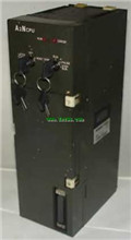
Product model: A2NCPUR21-S1
Name: PLC
Brand: MITSUBISHI
Sort: Hardware User's Manual
File language: English
Download link: MITSUBISHI A2NCPUR21-S1 User's Manual
Special multi axis positioning controller for NSD servo system.
Optical data communication line.
Program capacity: Max 60K step.
Input / output points: 1920 points.
When the switch is off, the diode does not emit light, and the transistor is not on the way. Internal circuit input signal.
It is through the input interface circuit to the external switch signal into PLC internal can accept the digital signal A2NCPUR21-S1 Hardware Manual A2NCPUR21-S1 User's Manual A2NCPUR21-S1
Photoelectric three levels: in the light of the light signal conduction, the degree of light signal and the intensity of the light signal.
The output signal has a linear relationship with the input signal in the linear operating region of the photoelectric coupler.
User program storage capacity: it is a measure of how much the user application can store the number of indicators A2NCPUR21-S1 Hardware Manual A2NCPUR21-S1 User's Manual.
Usually in words or K words as units. 16 bit binary number is a word,
Every 1024 words are 1K words. PLC to store instructions and data in words.
General logical operation instructions each account for 1 words. Timer / counter,
Shift instruction accounted for 2 words. Data operation instructions for 2~4 A2NCPUR21-S1 Hardware Manual A2NCPUR21-S1 User's Manual.
The length of time required to execute the instruction, the length of the user''s program, the type of instruction, and the speed of the CPU execution are very significant,
Generally, a scanning process, the fault diagnosis time,
Communication time, input sampling and output refresh time is less,
The execution time is accounted for the vast majority of.
The photoelectric coupler is composed of two luminous two extreme tubes and a photoelectric transistor.
Light emitting diode two: the input of a photo coupler and the change of electrical signal,
The light signal is generated by the light emitting diode, which is the same as the input signal.
The working process of the input interface circuit: when the switch is closed, the diode light,
The transistor is then guided to the internal circuit and input signal under the irradiation of the light. SI/QSI/H-PCF/ wide range H-PCF fiber optic cable.
Double loop.
PC inter network (management station / station) / remote I/O network (remote control station).
How to choose MITSUBISHI PLC.
MITSUBISHI PLC options include the choice of MITSUBISHI PLC models, capacity, I/O module, power, etc..
MITSUBISHI PLC distribution I/O points and design MITSUBISHI PLC peripheral hardware circuit
Draw the I/O point of the PLC and the input / output device connection diagram or the corresponding table,
This part also can be carried out in second steps.
Design PLC peripheral hardware circuit.
Draw the ellectrical wiring diagram of the other parts of the system,
Including the main circuit and the control circuit does not enter the PLC, etc A2NCPUR21-S1 Hardware Manual A2NCPUR21-S1 User's Manual. .
The electrical schematic diagram of the system compoosed of I/O PLC connection diagram and PLC peripheral electrical circuit diagram A2NCPUR21-S1 Hardware Manual A2NCPUR21-S1 User's Manual.
So far the system''s hardware electrical circuit has been determined.
Related products
MITSUBISHI
CPU unit
A2NCPU
Input and output points: 512 points.
Inp
MITSUBISHI
Moving CPU unit
A73CPUR21-S1
Multi axis positioning controller.
Coaxi
MITSUBISHI
CPU unit
A2NCPUP21-S3

Input and output points: 512 points.
Inp
MITSUBISHI
CPU unit
A2NCPUR21-S1
Input and output points: 1024 points.
In