Brand Sort:
MITSUBISHI
A1SJCPU-S8 Market price | A1SJCPU-S8 Introduction
- Brand: MITSUBISHI
- Country: JAPAN
- Name: CPU unit
- Model: A1SJCPU-S8
- Price: U.S.$ 101.69
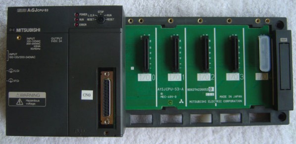
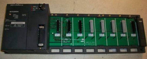
MITSUBISHI A1SJCPU-S8
8 slots.
Power supply unit.
QnA series unit installation.
High speed access.
CE logo fit.
I/O points is an important indicator of PLC.
Reasonable selection of I/O points can not only satisfy the control requirements of the system,
And the total investment of the system is the lowest.
The input and output points and types of PLC should be determined according to the analog quantity and switch quantity of the controlled object,
Generally an input / output element to take up an input / output point A1SJCPU-S8
Taking into account the future adjustment and expansion,
In general should be estimated on the total number of points plus the amount of spare 20%~30%.
When the programmer input programinto the user program memory,
Then CPU according to the function of the system (the system program memory to explain the compiler),
Translate the user program into PLC internally recognized by the user to compile the program.
Relay output interface circuit of PLC
Working process: when the internal circuit output digital signal 1,
There is a current flowing through, the relay coil has a current, and then the normally open contact is closed,
Provide load current and voltage.
When the internal circuit outputs a digital signal 0, there is no current flowing through it,
The relay coil does not have a current, and the normally open contact is broken off,
A current or voltage that is disconnected from the load.
It is through the output interface circuit to the internal digital circuit into a signal to make the load action or not action. Drive: MR-H_ACN series built-in positioning function.
Rated output: 0.4KW.
In servo drive speed closed loop,
Rotor speed measurement accuracy is very important to improve the dynamic and static characteristics of the speed control loop.
In order to seek the balance between measurement precision and system cost, incremental photoelectric encoder is generally used as the speed measuring sensor,
The corresponding method is M/T velocity measurement.
Although the M/T measurement method has a certain measurement accuracy and a wide range of measurement,
But this method has its inherent defects,
Mainly includes: the measurement period must be detected at least one complete encoder pulse, limiting the minimum detectable speed.
2 control system for speed control of the timer switch is difficult to maintain synchronization,
Can not guarantee the accuracy of measurement in the situation where the speed change is larger.
Therefore, it is difficult to improve the speed tracking and control performance of servo drive by using the traditional speed loop design method.
A1SJCPU-S8 Operation manual/Instructions/Model selection sample download link: /searchDownload.html?Search=A1SJCPU-S8&select=5
...more relevant model market price >>>>
Related products
MITSUBISHI
CPU unit
A1SJCPU-S3

Program memory capacity: 8k.
Input / out
MITSUBISHI
General purpose CPU
Q00UJCPU-S8

8 modules can e installed.
Input / outp
MITSUBISHI
CPU with base plate
Q00JCPU-S8

DC5V DC current consumption: 0.23A.
Num

