 LK Automation Limited
Brand:
MITSUBISHI
A1SJCPU-S3 | MITSUBISHI CPU unit A1SJCPU-S3
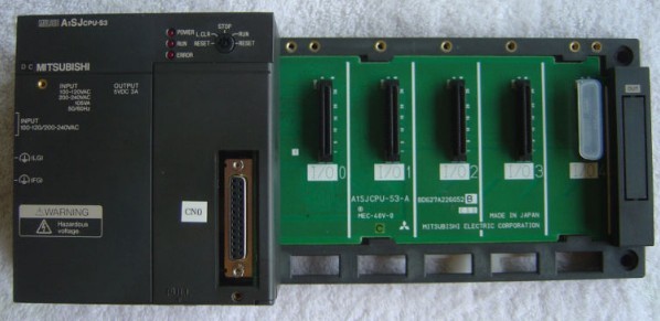
MITSUBISHI A1SJCPU-S3 Manual And Instructions
A1SJCPU-S3 datasheetPDF datasheet
A1SJCPU-S3 Common InstructionsProgramming Manual
A1SJCPU-S3 Dedicated InstructionsProgramming Manual
A1SJCPU-S3 FundamentalsProgramming Manual
MITSUBISHI A1SJCPU-S3 Product information and technical parameters:
Brand: MITSUBISHI
Name: CPU unit
Model: A1SJCPU-S3
Program memory capacity: 8k.
Input / output points: maximum 256 points.
With base plate and power supply.
PLC is the use of " sequential scanning, and constantly circulating " way to work.
That is, in the operation of CPU, PLC according to the user according to the control requirements of the coexistence of the user in the memory of the program,
According to the instruction sequence number (or address number) for periodic cyclic scan, such as no jump instruction,
From the first instruction to the user program execution sequence one by one, until the end of the program,
And then return to the first command, start the next round of the new scan, in the process of each scan,
Also complete the sampling of the input signal and the output status of the refresh and other work.
With the rapid development of microprocessor, computer and digital communication technology,
Computer control has been extended to almost all industrial fields.
Modern society requires manufacturing to respond quickly to market demand,
Production of small quantities, multi varieties, multi specifications, low cost and high quality products,
In order to meet this requirement,
Production equipment and automatic production line control system must have high reliability and flexibility,
PLC programming is to comply with the requirements of the emergence of it is based on a microprocessor based general industrial control device.
PLC programming is a digital computing operation of the electronic system,
Designed for applications in industrial environments.
It uses programmable memory,
An instruction used to perform logical operations, sequence control, timing, counting and arithmetic operations in its internal storage,
And through the digital, analog input and output, control of various types of machinery or production process.
Programmable controller and related equipment,
Should be easy to make the industrial control system to form a whole, easy to expand the principle design of its functions.
...More relevant models >>>>
A1SJCPU-S3 datasheetPDF datasheet
A1SJCPU-S3 Common InstructionsProgramming Manual
A1SJCPU-S3 Dedicated InstructionsProgramming Manual
A1SJCPU-S3 FundamentalsProgramming Manual
MITSUBISHI A1SJCPU-S3 Product information and technical parameters:
Brand: MITSUBISHI
Name: CPU unit
Model: A1SJCPU-S3
Program memory capacity: 8k.
Input / output points: maximum 256 points.
With base plate and power supply.
PLC is the use of " sequential scanning, and constantly circulating " way to work.
That is, in the operation of CPU, PLC according to the user according to the control requirements of the coexistence of the user in the memory of the program,
According to the instruction sequence number (or address number) for periodic cyclic scan, such as no jump instruction,
From the first instruction to the user program execution sequence one by one, until the end of the program,
And then return to the first command, start the next round of the new scan, in the process of each scan,
Also complete the sampling of the input signal and the output status of the refresh and other work.
With the rapid development of microprocessor, computer and digital communication technology,
Computer control has been extended to almost all industrial fields.
Modern society requires manufacturing to respond quickly to market demand,
Production of small quantities, multi varieties, multi specifications, low cost and high quality products,
In order to meet this requirement,
Production equipment and automatic production line control system must have high reliability and flexibility,
PLC programming is to comply with the requirements of the emergence of it is based on a microprocessor based general industrial control device.
PLC programming is a digital computing operation of the electronic system,
Designed for applications in industrial environments.
It uses programmable memory,
An instruction used to perform logical operations, sequence control, timing, counting and arithmetic operations in its internal storage,
And through the digital, analog input and output, control of various types of machinery or production process.
Programmable controller and related equipment,
Should be easy to make the industrial control system to form a whole, easy to expand the principle design of its functions.
Cable length: 3 meters
Extending cable to connect CPU main substrate and extended substrate,
According to the model can provide different cable length,
If you need to connect the AnN type expansion substrate is required,
Selection of A1SC05NB (A1SC07NB) cable. Axis of control: 2 axis linkage, 2 axis independence MITSUBISHI A1SJCPU-S3.
Interpolation function: 2 axis linear interpolation, 2 axis arc interpolation A1SJCPU-S3
A1SD75 series components show the MITSUBISHI in the manufacture and design of CNC, frequency converter,
Integrated technical experience in servo system and PLC.
These components have a wealth of features that are sufficient to meet the highest requirements in the application of positioning control.
Up to 3 axis linkage operation,
In low cost motion control applications, this component can be used to control the operation of a multi - to 3 axis, which can be used to account for only one slot MITSUBISHI A1SJCPU-S3. SRAM memory card.
RAM capacity: 128KB. Program memory capacity: 8k.
Input / output points: maximum 256 points.
A scan cycle of PLC must pass through three stages: input sampling, program execution and output refresh MITSUBISHI A1SJCPU-S3.
PLC in the input sampling phase: first of all, in order to scan the sequence of all existing input latches in the input terminal of the state or input data read,
And write it into the corresponding input status register,
Refresh the input, then close the input port, enter the program execution stage. Type of input: DC source.
Input points: 32 points.
Input voltage: DC12/24.
Input current: 3/7mA.
Connection mode: terminal row.
Common common point: 32.
Sequential function flow chart language is designed to satisfy the sequential logic control.
The process of sequential process action is divided into steps and transformation conditions,
According to the transfer condition, the control system is distributed in the function flow sequence,
Step by step according to the sequence of actions.
Each step represents a control function, represented by the box.
In the box, the ladder logic is used to complete the task of the corresponding control function.
This programming language makes the program structure clear and easy to read and maintain,
Greatly reduce the programming workload, shorten the programming and debugging time.
Used in the system of the size of the school, procedures for more complex occasions.
Sequence function flow chart programming language features: to function as the main line, in accordance with the functionaal flow of the order of distribution, clear, easy to understand the user program,
Avoid the defect of ladder diagram or other languages,
At the same time, the use of ladder language to avoid the use of ladder programming,
Due to the compllicated mechanical interlock, the structure of the user program is complex and difficult to understand,
User program scan time is also greatly reduced A1SJCPU-S3 A1SJCPU-S3.
...More relevant models >>>>