LK Automation Limited
Download Sort:
MITSUBISHI
MITSUBISHI A2NCPU Manual A2NCPU User's Manual
Product model: A2NCPU
Name: PLC
Brand: MITSUBISHI
Sort: User's Manual
File language: English
Download link: MITSUBISHI A2NCPU User's Manual
16 channels.
Input: DC-10 ~ 10V, DC-20 ~ 20mA.
Output (resolution): 0 ~ 4000, 0 ~ 8000, 0 ~ 12000.
38 point terminal station.
Analog I/P multiplexing unit.
Detailed analysis of the process and work characteristics of the controlled object,
To understand the coordination between the controlled object machine, electricity and liquid,
The control requirements of the controlled object for MITSUBISHI PLC control system are put forward,
Determine the control program, to develop a design task book A2NCPU Manual A2NCPU User's Manual A2NCPU
How to determine the input / output device of MITSUBISHI plc.
According to the control requirements of the system,
All input devices and output devices required for the determination of the system,
To determine the input / output device related to the MITSUBISHI PLC,
To determine the I/O PLC points A2NCPU Manual A2NCPU User's Manual. Axis of control: 1.
A1SD75 series components show the MITSUBISHI in the manufacture and design of CNC, frequency converter,
Integrated technical experience in servo system and PLC.
These components have a wealth of features that are sufficient to meet the highest requirements in the application of positioning control A2NCPU Manual A2NCPU User's Manual.
A1SD75M, SCC net compatible controller, SSC network is the MITSUBISHI servo system control network.
In this network, the MR-H-13, MR-J-B, and MR-J2 servo amplifiers can be connected to a controller via a network system,
The connection is replaced by a pulse sequence and a voltage signal. Input voltage range: AC100-120V/AC200-240V.
Output voltage: DC5V.
Output current: 8A.
For Q4ARCPU.
The control module monitors the power supply, the error
CPU state,
And its own error state.
It sends out
Error signal a6raf and open the corresponding
Relay output.
I/O points is an important indicator of PLC.
Reasonable selection of I/O points can not only satisfy the control requirements of the system,
And the total investment of the system is the lowest.
The input and output points and types of PLC should be determined according to the analog quantity and switch quantity of the controlled object,
Generally an input / output element to take up an input / output point A2NCPU Manual A2NCPU User's Manual.
Taking into account the future adjustment and expansion,
In general should be estimaated on the total number of points plus the amount of spare 20%~30% A2NCPU Manual A2NCPU User's Manual.
The following describes the centralized control system I/O points of the estimate.
Related products
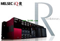
MITSUBISHI
Movement CPU
R32MTCPU

"Axis of control: 32.
Program language:
MITSUBISHI
CPU with base plate
Q00JCPU
Program capacity: 8K step.
Input / outpu
MITSUBISHI
CPU unit
A3NCPU
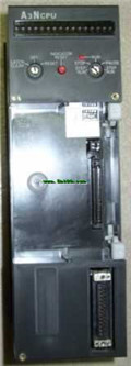
Input and output points: 2048 points.
In