LK Automation Limited
Download Sort:
MITSUBISHI
MITSUBISHI A2CJCPU Hardware Manual A2CJCPU User's Manual
Product model: A2CJCPU
Name: PLC
Brand: MITSUBISHI
Sort: Hardware User's Manual
File language: English
Download link: MITSUBISHI A2CJCPU User's Manual
Video display function: NTSC / PAL input system, 4CH.
RGB display function: analog RGB input system, 1CH.
Applicable model: A985GOT-V. A7HGP/A6GPP-CPU connection.
Length: 30m. Fast connector type.
Current input.
Number of channels: 8 channels.
Occupied the number of stations: Ver.1 mode occupied 3 stations, Ver A2CJCPU Hardware Manual A2CJCPU User's Manual. 2 mode occupied 1 stations.
Station type: remote equipment station A2CJCPU
MITSUBISHI PLC hardware implementation
Hardware implementation is mainly for the control cabinet and other hardware design and field construction.
Design control cabinet and the operating table and other parts of the electrical wiring diagram and wiring diagram.
Electrical interconnection diagram of each part of the design system A2CJCPU Hardware Manual A2CJCPU User's Manual.
According to the construction drawings of the site wiring, and carry out a detailed inspection.
Because the program design and hardware implementation can be carried out at the same time,
So the design cycle of the MITSUBISHI PLC control system can be greatly reduced.
MITSUBISHI PLC online debugging.
On-line debugging is the process that will through the simulation debugging to further carry on the on-line unification to adjust A2CJCPU Hardware Manual A2CJCPU User's Manual.
On-line debugging process should be step by step,
From MITSUBISHI PLC only connected to the input device, and then connect the output device, and then connect to the actual load and so on and so on step by step.
If you do not meet the requirements, the hardware and procedures for adjustment.
Usually only need to modify the part of the program can be. Input voltage range: DC110/125V.
Output voltage: DC5V.
Output current: 8A.
For Q4ARCPU.
The control module monitors the power supply, the error
CPU state,
And its own error state.
It sends out
Error signal a6raf and open the corresponding
Relay output.
I/O points is an important indicator of PLC.
Reasonable selection of I/O points can not only satisfy the control requirements of the system,
And the total investment of the system is the lowest.
The input and output points and types of PLC should be determined according to the analog quantity aand switch quantity of the controlled object,
Generally an input / output element to take up an input / output point A2CJCPU Hardware Manual A2CJCPU User's Manual.
Taking into account the future adjustment and expansion,
In general should be estimaated on the total number of points plus the amount of spare 20%~30% A2CJCPU Hardware Manual A2CJCPU User's Manual.
The following describes the centralized control system I/O points of the estimate.
Related products
MITSUBISHI
General purpose CPU
Q06UDHCPU
Input / output points: 4096 points.
Num
MITSUBISHI
Programmable logic controller CPU
R04ENCPU
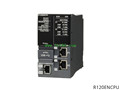
Operation control mode: stored procedure
MITSUBISHI
CPU unit
A3ACPU
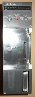
Input and output points: 2048 points.
In