 LK Automation Limited
Download Sort:
MITSUBISHI
MITSUBISHI A172SHCPU Dedicated Instructions Manual A172SHCPU Programming Manual
Product model: A172SHCPU
Name: PLC
Brand: MITSUBISHI
Sort: Dedicated Instructions Programming Manual
File language: English
Download link: MITSUBISHI A172SHCPU Programming Manual
Input type: DC input, positive public end / negative public end.
Input points: 8 points.
Enter the response time: 10ms the following.
Rated input voltage / current: DC24V/7mA.
Output form: relay output.
Output points: 8 points.
OFF leakage current: -.
Output protection function: No.
Rated load voltage / current: DC12V/AC240V/2A A172SHCPU Dedicated Instructions Manual A172SHCPU Programming Manual.
External connection: 2 line /2 line type A172SHCPU
Type of input and output terminal.
Using 2 pieces of structure of the terminal units, maintenance can be maintained in the same line under the condition of the replacement module. Type of input: DC source.
Input points: 16 points.
Input voltage: DC24.
Input current: 7mA.
Connection mode: terminal row.
Common common point: 16 A172SHCPU Dedicated Instructions Manual A172SHCPU Programming Manual.
Sequential function flow chart language is designed to satisfy the sequential logic control.
The process of sequential process action is divided into steps and transformation conditions,
According to the transfer condition, the control system is distributed in the function flow sequence,
Step by step according to the sequence of actions.
Each step represents a control function, represented by the box A172SHCPU Dedicated Instructions Manual A172SHCPU Programming Manual.
In the box, the ladder logic is used to complete the task of the corresponding control function.
This programming language makes the program structure clear and easy to read and maintain,
Greatly reduce the programming workload, shorten the programming and debugging time.
Used in the system of the size of the school, procedures for more complex occasions.
Sequence function flow chart programming language features: to function as the main line, in accordance with the functional flow of the order of distribution, clear, easy to understand the user program,
Avoid the defect of ladder diagram or other languages,
At the same time, the use of ladder language to avoid the use of ladder programming,
Due to the complicated mechanical interlock, the structure of the user program is complex and difficult to understand,
User program scan time is also greatly reduced. 2 channels.
3 wire platinum measuring antibodies (Pt100, JPt100).
Transform speed: 40ms/1 channel.
20 point terminal station.
The popularization and application of PLC programming has been developed rapidly in our country,
It has been widely used in all kinds of mechanical equipment and production process of electrical control devices,
All walks of life have emerged a large number of application of PLC transformation of the results of the equipment.
Understand the working principle of PLC, have the ability to design, debug and maintain the PLC control system,
Has become the basic requirements of modern industry for electrical technicians and engineering students.
PLC user program is designed according to the control system of the process control requirements,
PLC programming language through the preparation of specifications, in accordance with the actual needs of the use of the function to design.
As long as the user can master some kind of standard programming language,
To be able to use PLC in the control system,
To achieve a variety of automatic control functions.
The instruction list programming language is a programming language similar to assembly language mnemonic,
As well as assembly language by the operation code and the number of operations.
In the case of the computer for the PLC handheld programmer compile user program.
At the same time, the programming language of the instruction list corresponds to the ladder diagram programming language,
In PLC programming software can be converted to each other. Figure 3 is the instruction sheet corresponding to the ladder diagram of figure 2PLC.
The characteristics of instruction table programming language is used to represent mnemonic operation function,
Easy to remember, easy to grasp;
In the handheld programmer on the keyboard using the mnemonic representation, easy to operate, can be programmed in computer;
There is a one-to-one correspondence between the ladder diagram and the ladder diagram. Its characteristics are basically consistent with the ladder diagram language.
Functional block diagram language is a kind of PLC programming language, which is similar to digital logic circuit.
The function module is used to represent the function of the module,
Different function modules have different functions.
Functional module figure programming language features: functional block diagram programming language is characterized by a functional module for the unit,
Analysis and understanding of the control scheme is simple and easy: function module is to use grapphical form of expression,
Intuitive, for a digital logic circuit based on the design of the staff is very easy to master the programming;
Control system with complex scale and coomplex control logic,
Because the function module diagram can clearly express the function relation, the programming debugging time is greatly reduced A172SHCPU Dedicated Instructions Manual A172SHCPU Programming Manual A172SHCPU Dedicated Instructions Manual A172SHCPU Programming Manual.
Related products
MITSUBISHI
General purpose CPU
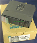
Q06UDHCPU
Input / output points: 4096 points.
Num
MITSUBISHI
High performance CPU
Q06HCPU
Program capacity: 60 K step.
Input / out
MITSUBISHI
Process CPU
Q12PRHCPU
Program capacity: 124 K step.
Input / ou