 LK Automation Limited
Download Sort:
MITSUBISHI
MITSUBISHI A2CJCPU-S3 Hardware Manual A2CJCPU-S3 User's Manual
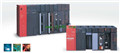
Product model: A2CJCPU-S3
Name: PLC
Brand: MITSUBISHI
Sort: Hardware User's Manual
File language: English
Download link: MITSUBISHI A2CJCPU-S3 User's Manual
Enter points: 64 points.
Input voltage: DC7V above.
Input response time: 16ms.
16 pin connector.
Output points: 64 points.
Output response time: 16ms.
Output type: transistor output.
32 pin connector.
Dynamic input and output.
Control solenoid valve required I/O points by the action principle of the solenoid valve can be known,
A single coil solenoid valve with PLC control to 2 input and 1 output,
A double coil solenoid valve requires 3 inputs and 2 outputs,
A button needs an input; a light sensitive switch needs 4 or 2 inputs,
A signal lamp needs 1 output, band switch,
Several bands are required for several inputs,
In general, a variety of position switches are required to take up 2 input points A2CJCPU-S3 Hardware Manual A2CJCPU-S3 User's Manual A2CJCPU-S3 Hardware Manual A2CJCPU-S3 User's Manual A2CJCPU-S3
MITSUBISHI PLC is the main product in the production of MITSUBISHI motor in Dalian.
It uses a kind of programmable memory for its internal storage procedures,
Execute logic operation, sequence control, timing, counting and arithmetic operations, user oriented instruction,
And through digital or analog input / output control of various types of machinery or production process.
The number of I/O thyristor DC motor control required tube DC motor speed control system is the main form of DC speed regulation,
The thyristor rectifier unit is used to supply power to the DC motor A2CJCPU-S3 Hardware Manual A2CJCPU-S3 User's Manual.
PLC control of the DC drive system, the input of the PLC in addition to the main signal outside the signal,
We need to consider the switching signal, the fault signal transmission device, brake signal and fan fault signal.
The output of the PLC mainly consider the speed command signal positive 1~3 level, 1~3 level, allowing reverse switching signal and brake open signal etc..
In general, a reversible DC drive system controlled by PLC is approximately 12 input points and 8 output points,
An irreversible DC drive system requires 9 inputs and 6 output points. 3C-2V/5C-2V coaxial cable.
Single bus.
PC inter network (management station / station) / remote I/O network (remote control station).
How to choose MITSUBISHI PLC.
MITSUBISHI PLC options include the choice of MITSUBISHI PLC models, capacity, I/O module, power, etc..
MITSUBISHI PLC distribution I/O points and design MITSUBISHI PLC peripheral hardware circuit
Draw the I/O point of the PLC and the input / output device connection diagram or the corresponding table,
This part also can be carried out in second steps.
Design PLC peripheral hardware circuit.
Draw thhe electrical wiring diagram of the other parts of the system,
Including the main circuit and the control circuit does not enter the PLC, etc A2CJCPU-S3 Hardware Manual A2CJCPU-S3 User's Manual. .
The electrical schematic diagram of the system compoosed of I/O PLC connection diagram and PLC peripheral electrical circuit diagram A2CJCPU-S3 Hardware Manual A2CJCPU-S3 User's Manual.
So far the system''s hardware electrical circuit has been determined.
Related products
MITSUBISHI
CPU unit
A2CJCPU

Input points 512,
CPU power supply,
Item

MITSUBISHI
Moving CPU unit
A73CPU-S3

Special multi axis positioning controlle
MITSUBISHI
CPU unit
A2CJCPU-S3
Input and output points: 512 points.
Inp