 LK Automation Limited
Brand:
MITSUBISHI
AJ71VP21 | MITSUBISHI Multiple system module AJ71VP21
MITSUBISHI AJ71VP21 Manual And Instructions
AJ71VP21 datasheetPDF datasheet
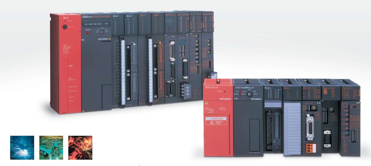
MITSUBISHI AJ71VP21 Product information and technical parameters:
Brand: MITSUBISHI
Name: Multiple system module
Model: AJ71VP21
Data communication line module (optical cable) Master / local station for A3VTS multiplex system
MITSUBISHI PLC detection, fault diagnosis and display and other procedures.
These procedures are relatively independent, generally in the basic completion of the program design and then add.
MITSUBISHI PLC protection and chain procedures.
Protection and chain is an indispensable part of the program, must be carefully considered.
It can avoid the control logic confusion caused by illegal operations.
...More relevant models >>>>
AJ71VP21 datasheetPDF datasheet
MITSUBISHI AJ71VP21 Product information and technical parameters:
Brand: MITSUBISHI
Name: Multiple system module
Model: AJ71VP21
Data communication line module (optical cable) Master / local station for A3VTS multiplex system
MITSUBISHI PLC detection, fault diagnosis and display and other procedures.
These procedures are relatively independent, generally in the basic completion of the program design and then add.
MITSUBISHI PLC protection and chain procedures.
Protection and chain is an indispensable part of the program, must be carefully considered.
It can avoid the control logic confusion caused by illegal operations.
10BASE-T.
For Q mode.
When communicating in the PLC network of MITSUBISHI,
There is no sense of difference and discontinuity in the network,
Can carry on the remote monitoring, modification, debugging and other work of data communication and program,
Without taking into account the level and type of network MITSUBISHI AJ71VP21.
MELSECNET/H and CC-Link use the way of loop communication,
Periodically automatically send and receive messages,
Does not require specialized data communication procedures,
Simple parameters can be set AJ71VP21
MELSECNET/H and CC-Link are used to transmit and receive the broadcast mode,
This can be done on the network data sharing.
For the use of Ethernet, MELSECNET/H, CC-Link network,
Can set the network parameters and various functions, simple and convenient in the Developer GX software screen MITSUBISHI AJ71VP21. Input voltage range: AC100-120V/AC200-240V.
Output voltage: DC24V.
Output current: 1.2A additional power supply unit.
I/O points is an important indicator of PLC.
Reasonable selection of I/O points can not only satisfy the control requirements of the system,
And the total investment of the system is the lowest MITSUBISHI AJ71VP21.
The input and output points and types of PLC should be determined according to the analog quantity and switch quantity of the controlled object,
Generally an input / output element to take up an input / output point.
Taking into account the future adjustment and expansion,
In general should be estimated on the total number of points plus the amount of spare 20%~30%.
The following describes the centralized control system I/O points of the estimate. GI fiber optic cable.
Dual loop for Q mode.
Remote I/O network (remote control station).
How to choose MITSUBISHI PLC.
MITSUBISHI PLC options include the choice of MITSUBISHI PLC models, capacity, I/O module, power, etc..
MITSUBISHI PLC distribution I/O points and design MITSUBISHI PLC peripheral hardware circuit
Draw the I/O point of the PLC and the input / output device connection diagram or the corresponding table,
This part also can be carried out in second steps.
Dessign PLC peripheral hardware circuit AJ71VP21.
Draw the electrical wiring diagram of the other parts of the system,
Including the main circuit and the control circuit does not enter the PLC, etc..
The electrical schematic diagram of the system compoosed of I/O PLC connection diagram and PLC peripheral electrical circuit diagram AJ71VP21.
So far the system''s hardware electrical circuit has been determined.
...More relevant models >>>>