 LK Automation Limited
Brand:
MITSUBISHI
A3VTU | MITSUBISHI Multiple system module A3VTU
MITSUBISHI A3VTU Manual And Instructions
A3VTU datasheetPDF datasheet
MITSUBISHI A3VTU Product information and technical parameters:
Brand: MITSUBISHI
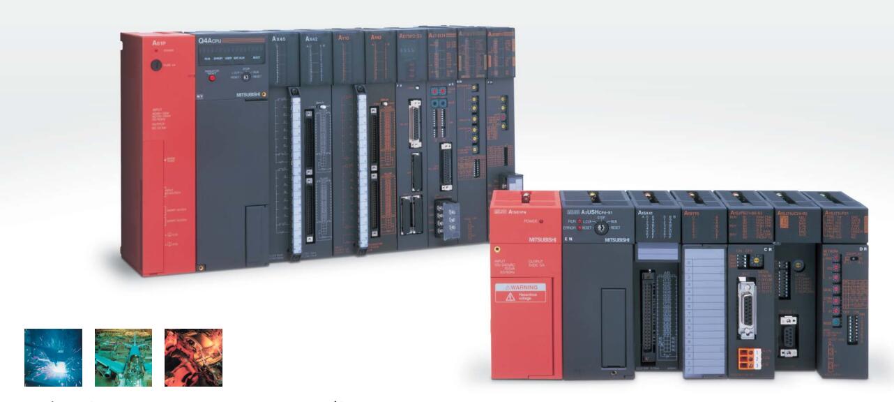
Name: Multiple system module
Model: A3VTU
Module for A3VTS multiplex system.
MITSUBISHI PLC detection, fault diagnosis and display and other procedures.
These procedures are relatively independent, generally in the basic completion of the program design and then add.
MITSUBISHI PLC protection and chain procedures.
Protection and chain is an indispensable part of the program, must be carefully considered.
It can avoid the control logic confusion caused by illegal operations.
...More relevant models >>>>
A3VTU datasheetPDF datasheet
MITSUBISHI A3VTU Product information and technical parameters:
Brand: MITSUBISHI
Name: Multiple system module
Model: A3VTU
Module for A3VTS multiplex system.
MITSUBISHI PLC detection, fault diagnosis and display and other procedures.
These procedures are relatively independent, generally in the basic completion of the program design and then add.
MITSUBISHI PLC protection and chain procedures.
Protection and chain is an indispensable part of the program, must be carefully considered.
It can avoid the control logic confusion caused by illegal operations.
MELSECNET/10, MELSECNET/H coaxial.
Input voltage: DC24V.
How to choose MITSUBISHI PLC.
MITSUBISHI PLC options include the choice of MITSUBISHI PLC models, capacity, I/O module, power, etc..
MITSUBISHI PLC distribution I/O points and design MITSUBISHI PLC peripheral hardware circuit
Draw the I/O point of the PLC and the input / output device connection diagram or the corresponding table,
This part also can be carried out in second steps MITSUBISHI A3VTU A3VTU
Design PLC peripheral hardware circuit.
Draw the electrical wiring diagram of the other parts of the system,
Including the main circuit and the control circuit does not enter the PLC, etc..
The electrical schematic diagram of the system composed of I/O PLC connection diagram and PLC peripheral electrical circuit diagram MITSUBISHI A3VTU.
So far the system''s hardware electrical circuit has been determined. A7HGP/A6GPP-CPU connection.
Length: 30m. RS-232:1, RS-422/485:1.
Transmission speed: 0.3 ~ 19.2kpbs.
Computer connection function.
A3VCPU special.
Printer / peripheral device connection, BASIC language function.
How to choose MITSUBISHI PLC.
MITSUBISHI PLC options include the choice of MITSUBISHI PLC models, capacity, I/O module, power, etc MITSUBISHI A3VTU. .
MITSUBISHI PLC distribution I/O points and design MITSUBISHI PLC peripheral hardware circuit
Draw the I/O point of the PLC and the input / output device connection diagram or the corresponding table,
This part also can be carried out in second steps.
Design PLC peripheral hardware circuit.
Draw the electrical wiring diagram of the other parts of the system,
Including the main circuit and the control circuit does not enter the PLC, etc..
The electrical schematic diagram of the system composed of I/O PLC connection diagram and PLC peripheral electrical circuit diagram.
So far the system''s hardware electrical circuit has been determined. A65B/A68B/A55B/A58B connection cable.
Length: 1000mm. RS-422 1 channel.
Communication speed: 500kbps.
Connection points: 512 points (set switch) /3584 point (the upper controller).
How to determine the input / output device of MITSUBISHI plc.
According to the control requirements of the system,
All input devices and output devices required for the determination of the system,
To determine the input / output device related to tthe MITSUBISHI PLC,
To determine the I/O PLC points A3VTU.
Detailed analysis of the process and work characteristics of the controlled object,
To understand the coordination between the controlled object machine, electricity and liquid,
The control requirements of the controlled object for MITSUBISHI PLC control system are put forward,
Determine the control program, to develop a design task book A3VTU.
...More relevant models >>>>