 LK Automation Limited
Brand:
MITSUBISHI
A2ACPUP21 | MITSUBISHI CPU unit A2ACPUP21
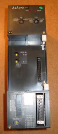
MITSUBISHI A2ACPUP21 Manual And Instructions
A2ACPUP21 datasheetPDF datasheet
A2ACPUP21 Common InstructionsProgramming Manual
A2ACPUP21 User's Manual
A2ACPUP21 HardwareUser's Manual
A2ACPUP21 AD57 control InstructionsProgramming Manual
A2ACPUP21 Dedicated InstructionsProgramming Manual
A2ACPUP21 FundamentalsProgramming Manual
A2ACPUP21 PID Control InstructionsProgramming Manual
MITSUBISHI A2ACPUP21 Product information and technical parameters:
Brand: MITSUBISHI
Name: CPU unit
Model: A2ACPUP21
Input and output points: 512 points.
Input / output data points: 512 points.
Program capacity: 14K.
Basic command processing speed (LD command) s:0.20.
Optical data communication line.
Each scanning process. Focus on the input signal sampling. Focus on the output signal to refresh.
Input refresh process. When the input port is closed,
Program in the implementation phase, the input end of a new state, the new state can not be read.
Only when the program is scanned, the new state is read.
A scan cycle is divided into the input sample, the program execution, the output refresh.
The contents of the component image register are changed with the change of the execution of the program.
The length of the scan cycle is determined by the three.
CPU the speed of executing instructions.
Time of instruction.
Instruction count.
Due to the adoption of centralized sampling.
Centralized output mode.
There exist input / output hysteresis phenomena, i.e., the input / output response delay.
User program storage capacity: it is a measure of how much the user application can store the number of indicators.
Usually in words or K words as units. 16 bit binary number is a word,
Every 1024 words are 1K words. PLC to store instructions and data in words.
General logical operation instructions each account for 1 words. Timer / counter,
Shift instruction accounted for 2 words. Data operation instructions for 2~4.
...More relevant models >>>>
A2ACPUP21 datasheetPDF datasheet
A2ACPUP21 Common InstructionsProgramming Manual
A2ACPUP21 User's Manual
A2ACPUP21 HardwareUser's Manual
A2ACPUP21 AD57 control InstructionsProgramming Manual
A2ACPUP21 Dedicated InstructionsProgramming Manual
A2ACPUP21 FundamentalsProgramming Manual
A2ACPUP21 PID Control InstructionsProgramming Manual
MITSUBISHI A2ACPUP21 Product information and technical parameters:
Brand: MITSUBISHI
Name: CPU unit
Model: A2ACPUP21
Input and output points: 512 points.
Input / output data points: 512 points.
Program capacity: 14K.
Basic command processing speed (LD command) s:0.20.
Optical data communication line.
Each scanning process. Focus on the input signal sampling. Focus on the output signal to refresh.
Input refresh process. When the input port is closed,
Program in the implementation phase, the input end of a new state, the new state can not be read.
Only when the program is scanned, the new state is read.
A scan cycle is divided into the input sample, the program execution, the output refresh.
The contents of the component image register are changed with the change of the execution of the program.
The length of the scan cycle is determined by the three.
CPU the speed of executing instructions.
Time of instruction.
Instruction count.
Due to the adoption of centralized sampling.
Centralized output mode.
There exist input / output hysteresis phenomena, i.e., the input / output response delay.
User program storage capacity: it is a measure of how much the user application can store the number of indicators.
Usually in words or K words as units. 16 bit binary number is a word,
Every 1024 words are 1K words. PLC to store instructions and data in words.
General logical operation instructions each account for 1 words. Timer / counter,
Shift instruction accounted for 2 words. Data operation instructions for 2~4.
SI/QSI/H-PCF/ wide range H-PCF fiber optic cable.
Double loop.
Remote I/O network (remote control station).
How to choose MITSUBISHI PLC.
MITSUBISHI PLC options include the choice of MITSUBISHI PLC models, capacity, I/O module, power, etc..
MITSUBISHI PLC distribution I/O points and design MITSUBISHI PLC peripheral hardware circuit
Draw the I/O point of the PLC and the input / output device connection diagram or the corresponding table,
This part also can be carried out in second steps MITSUBISHI A2ACPUP21 A2ACPUP21
Design PLC peripheral hardware circuit.
Draw the electrical wiring diagram of the other parts of the system,
Including the main circuit and the control circuit does not enter the PLC, etc..
The electrical schematic diagram of the system composed of I/O PLC connection diagram and PLC peripheral electrical circuit diagram MITSUBISHI A2ACPUP21.
So far the system''s hardware electrical circuit has been determined. NSD servo system.
A73CPU (P21/R21) -S3 dedicated.
Relay output interface circuit of PLC
Working process: when the internal circuit output digital signal 1,
There is a current flowing through, the relay coil has a current, and then the normally open contact is closed,
Provide load current and voltage MITSUBISHI A2ACPUP21.
When the internal circuit outputs a digital signal 0, there is no current flowing through it,
The relay coil does not have a current, and the normally open contact is broken off,
A current or voltage that is disconnected from the load.
It is through the output interface circuit to the internal digital circuit into a signal to make the load action or not action.
When the programmer input programinto the user program memory,
Then CPU according to the function of the system (the system program memory to explain the compiler),
Translate the user program into PLC internally recognized by the user to compile the program.
I/O points is an important indicator of PLC.
Reasonable selection of I/O points can not only satisfy the control requirements of the system,
And the total investment of the system is the lowest.
The input and output points and types of PLC should be determinned according to the analog quantity and switch quantity of the controlled object,
Generally an input / output element to take up an input / output point A2ACPUP21.
Taking into account the future adjustment and expansion,
In general should be estimaated on the total number of points plus the amount of spare 20%~30% A2ACPUP21.
The following describes the centralized control system I/O points of the estimate.
...More relevant models >>>>