 LK Automation Limited
Brand:
MITSUBISHI
A1SY71 | MITSUBISHI output module A1SY71
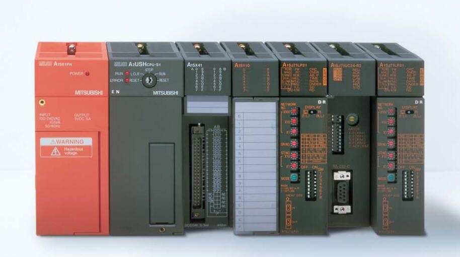
MITSUBISHI A1SY71 Manual And Instructions
A1SY71 datasheetPDF datasheet
A1SY71 User's Manual
MITSUBISHI A1SY71 Product information and technical parameters:
Brand: MITSUBISHI
Name: output module
Model: A1SY71
Output type: transistor drain.
Output points: 32 points.
Load voltage: DC5/12.
Load current: 0.016A.
Connection: FCN connector.
Common public end points: 32.
Switching value, also known as logic, refers to only two values, 0 or 1, ON or OFF.
It is the most common control, it is the advantage of PLC control,
Is also the most basic application of PLC.
Switch volume control is designed to,
According to the current input combination of the switch quantity and the history of the input sequence,
So that PLC generates the corresponding switching output,
In order to make the system work in a certain order.
So, sometimes also known as the order control.
And sequential control is divided into manual, semi-automatic or automatic.
And the control principle is decentralized, centralized and hybrid control three.
...More relevant models >>>>
A1SY71 datasheetPDF datasheet
A1SY71 User's Manual
MITSUBISHI A1SY71 Product information and technical parameters:
Brand: MITSUBISHI
Name: output module
Model: A1SY71
Output type: transistor drain.
Output points: 32 points.
Load voltage: DC5/12.
Load current: 0.016A.
Connection: FCN connector.
Common public end points: 32.
Switching value, also known as logic, refers to only two values, 0 or 1, ON or OFF.
It is the most common control, it is the advantage of PLC control,
Is also the most basic application of PLC.
Switch volume control is designed to,
According to the current input combination of the switch quantity and the history of the input sequence,
So that PLC generates the corresponding switching output,
In order to make the system work in a certain order.
So, sometimes also known as the order control.
And sequential control is divided into manual, semi-automatic or automatic.
And the control principle is decentralized, centralized and hybrid control three.
Using a modem middle modular connector unit faces to transmit data transmission speed: 0.3-14.4kbps.
PLC is the use of " sequential scanning, and constantly circulating " way to work.
That is, in the operation of CPU, PLC according to the user according to the control requirements of the coexistence of the user in the memory of the program,
According to the instruction sequence number (or address number) for periodic cyclic scan, such as no jump instruction,
From the first instruction to the user program execution sequence one by one, until the end of the program,
And then return to the first command, start the next round of the new scan, in the process of each scan,
Also complete the sampling of the input signal and the output status of the refresh and other work MITSUBISHI A1SY71 MITSUBISHI A1SY71 A1SY71
PLC is the use of " sequential scanning, and constantly circulating " way to work.
That is, in the operation of CPU, PLC according to the user according to the control requirements of the coexistence of the user in the memory of the program,
According to the instruction sequence number (or address number) for periodic cyclic scan, such as no jump instruction,
From the first instruction to the user program execution sequence one by one, until the end of the program,
And then return to the first command, start the next round of the new scan, in the process of each scan,
Also complete the sampling of the input signal and the output status of the refresh and other work MITSUBISHI A1SY71. Interface: RS232C.
Transmission distance: 15 meters.
A1SJ71UC24-R2/R4/PR computer communication components can communicate with PLC, such as computers and other external intelligent devices, and the components are as follows:
Full / half duplex transmission.
4 special communication protocols.
No protocol and bidirectional mode.
Protocol selection switch function.
The optional baud rate, the highest 19.2K.
Since the echo diagnostic test. Type of input: DC source.
Input points: 32 points.
Input voltage: DC24.
Input current: 7mA.
Connection mode: terminal row.
Common common point: 32.
Sequential function flow chart language is designed to satisfy the sequential logic control.
The process of sequential process action is divided into steps and transformation conditions,
According to the transfer condition, the control system is distributed in the function flow sequence,
Step by step according to the sequence of actions.
Each step represents a control function, represented by the box.
In the box, the ladder logic is used to complete the task of the corresponding control function.
This programming language makes the program structure clear and easy to read and maintain,
Greatly reduce the programming workload, shorten the programming and debugging time.
Used in the system of the size of the school, procedures for more complex occasions.
Sequence function flow chart programming language features: to function as the main line, in accordance with the functtional flow of the order of distribution, clear, easy to understand the user program,
Avoid the defect of ladder diagram or other languages,
At the same time, the use of ladder language to avoid the use of ladder programming,
Due to the compllicated mechanical interlock, the structure of the user program is complex and difficult to understand,
User program scan time is also greatly reduced A1SY71 A1SY71.
PLC is the use of " sequential scanning, and constantly circulating " way to work.
That is, in the operation of CPU, PLC according to the user according to the control requirements of the coexistence of the user in the memory of the program,
According to the instruction sequence number (or address number) for periodic cyclic scan, such as no jump instruction,
From the first instruction to the user program execution sequence one by one, until the end of the program,
And then return to the first command, start the next round of the new scan, in the process of each scan,
Also complete the sampling of the input signal and the output status of the refresh and other work MITSUBISHI A1SY71 MITSUBISHI A1SY71 A1SY71
PLC is the use of " sequential scanning, and constantly circulating " way to work.
That is, in the operation of CPU, PLC according to the user according to the control requirements of the coexistence of the user in the memory of the program,
According to the instruction sequence number (or address number) for periodic cyclic scan, such as no jump instruction,
From the first instruction to the user program execution sequence one by one, until the end of the program,
And then return to the first command, start the next round of the new scan, in the process of each scan,
Also complete the sampling of the input signal and the output status of the refresh and other work MITSUBISHI A1SY71. Interface: RS232C.
Transmission distance: 15 meters.
A1SJ71UC24-R2/R4/PR computer communication components can communicate with PLC, such as computers and other external intelligent devices, and the components are as follows:
Full / half duplex transmission.
4 special communication protocols.
No protocol and bidirectional mode.
Protocol selection switch function.
The optional baud rate, the highest 19.2K.
Since the echo diagnostic test. Type of input: DC source.
Input points: 32 points.
Input voltage: DC24.
Input current: 7mA.
Connection mode: terminal row.
Common common point: 32.
Sequential function flow chart language is designed to satisfy the sequential logic control.
The process of sequential process action is divided into steps and transformation conditions,
According to the transfer condition, the control system is distributed in the function flow sequence,
Step by step according to the sequence of actions.
Each step represents a control function, represented by the box.
In the box, the ladder logic is used to complete the task of the corresponding control function.
This programming language makes the program structure clear and easy to read and maintain,
Greatly reduce the programming workload, shorten the programming and debugging time.
Used in the system of the size of the school, procedures for more complex occasions.
Sequence function flow chart programming language features: to function as the main line, in accordance with the functtional flow of the order of distribution, clear, easy to understand the user program,
Avoid the defect of ladder diagram or other languages,
At the same time, the use of ladder language to avoid the use of ladder programming,
Due to the compllicated mechanical interlock, the structure of the user program is complex and difficult to understand,
User program scan time is also greatly reduced A1SY71 A1SY71.
...More relevant models >>>>