 LK Automation Limited
Brand:
MITSUBISHI
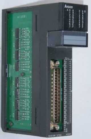
A1SX81 | MITSUBISHI DC source type input module A1SX81
MITSUBISHI A1SX81 Manual And Instructions
A1SX81 datasheetPDF datasheet
A1SX81 User's Manual
MITSUBISHI A1SX81 Product information and technical parameters:
Brand: MITSUBISHI
Name: DC source type input module
Model: A1SX81
Type of input: DC source.
Input points: 32 points.
Input voltage: DC12/24.
Input current: 3/7mA.
Connection mode: terminal row.
Common common point: 32.
Sequential function flow chart language is designed to satisfy the sequential logic control.
The process of sequential process action is divided into steps and transformation conditions,
According to the transfer condition, the control system is distributed in the function flow sequence,
Step by step according to the sequence of actions.
Each step represents a control function, represented by the box.
In the box, the ladder logic is used to complete the task of the corresponding control function.
This programming language makes the program structure clear and easy to read and maintain,
Greatly reduce the programming workload, shorten the programming and debugging time.
Used in the system of the size of the school, procedures for more complex occasions.
Sequence function flow chart programming language features: to function as the main line, in accordance with the functional flow of the order of distribution, clear, easy to understand the user program,
Avoid the defect of ladder diagram or other languages,
At the same time, the use of ladder language to avoid the use of ladder programming,
Due to the complicated mechanical interlock, the structure of the user program is complex and difficult to understand,
User program scan time is also greatly reduced.
...More relevant models >>>>
A1SX81 datasheetPDF datasheet
A1SX81 User's Manual
MITSUBISHI A1SX81 Product information and technical parameters:
Brand: MITSUBISHI
Name: DC source type input module
Model: A1SX81
Type of input: DC source.
Input points: 32 points.
Input voltage: DC12/24.
Input current: 3/7mA.
Connection mode: terminal row.
Common common point: 32.
Sequential function flow chart language is designed to satisfy the sequential logic control.
The process of sequential process action is divided into steps and transformation conditions,
According to the transfer condition, the control system is distributed in the function flow sequence,
Step by step according to the sequence of actions.
Each step represents a control function, represented by the box.
In the box, the ladder logic is used to complete the task of the corresponding control function.
This programming language makes the program structure clear and easy to read and maintain,
Greatly reduce the programming workload, shorten the programming and debugging time.
Used in the system of the size of the school, procedures for more complex occasions.
Sequence function flow chart programming language features: to function as the main line, in accordance with the functional flow of the order of distribution, clear, easy to understand the user program,
Avoid the defect of ladder diagram or other languages,
At the same time, the use of ladder language to avoid the use of ladder programming,
Due to the complicated mechanical interlock, the structure of the user program is complex and difficult to understand,
User program scan time is also greatly reduced.
I/O slots: 5 slots.
Outline dimension: 325*130.
CPU basic board can be plugged into 1 power modules,
1 CPU components and a maximum of 2, 3, 5, or 8 single slot size special function components and I/O components are respectively inserted and arranged.
Expansion ports are arranged on both sides of the base plate,
For connecting the expansion board for MITSUBISHI A1SX81.
Up to 3 extension substrates A1SX81 Signal transmission device B/NET interface device for power distribution control equipment
The response time of PLC is the interval between the time of the change of the external output signal of the PLC and the time of the change of the external output signal which is controlled by it,
Lag time, this is the time constant of the input circuit,
The time constant of the output circuit, the arrangement of the user statement and the use of the instruction,
The cycle scan mode of PLC and the way of PLC to refresh the I/O and so on MITSUBISHI A1SX81.
This phenomenon is called the I/O delay time effect.
Input status and input information input from the input interface,
CPU will be stored in the working data memory or in the input image register MITSUBISHI A1SX81.
And then combine the data and the program with CPU.
The result is stored in the output image register or the working data memory,
And then output to the output interface, control the external drive. Enter 8 points.
7mA DC24V.
Response time: 12ms.
8 positive, 1 public to reduce the public in common use.
Output 8 points.
DC24V/AC240V, 2A/1 point, 8A/1 common.
Response time: 12ms.
8 point 1 public 20 point terminal.
PLC is introduced by the relay control technology after the development of micro processing technology,
Can be easily and reliably used for switching control.
As the analog quantity can be converted into digital quantity, the number of digital quantity is just a number of switching value,
Therefore, after the conversion of analog, PLC can also be reliable for processing control.
Because the continuous production process often has the analog quantity, the analog quantity control is sometimes called process control.
Analog quantity is not electricity, and PLC can only handle digital quantity, quantity of electricity.
All to realize the conversion between them to have the sensor, the analog quantity into a number of power.
If this power is not standard, but also through the transmitter,
The non-standard power into a standard electrical signal, such as 1-5V, 4-20mA, 0-10V, etc..
At the same time, there is also an analog input unit (A/D),
Transform these standarrd electrical signals into digital signals,
The analog output unit (D/A), in order to transform the digital quantity after PLC processing into analog quantity -- standard electric signal A1SX81.
So the standard telecommunication number, the conversiion between the number of operations to use a variety of computing A1SX81.
This requires the resolution of the analog unit and the standard electrical signal.
...More relevant models >>>>