 LK Automation Limited
Brand:
MITSUBISHI
A173UHCPU-S1 | MITSUBISHI cpu module A173UHCPU-S1
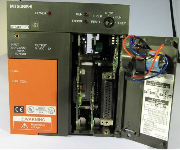
MITSUBISHI A173UHCPU-S1 Manual And Instructions
A173UHCPU-S1 datasheetPDF datasheet
A173UHCPU-S1 Common InstructionsProgramming Manual
A173UHCPU-S1 Dedicated InstructionsProgramming Manual
A173UHCPU-S1 FundamentalsProgramming Manual
A173UHCPU-S1 SV13/22 SFCProgramming Manual
MITSUBISHI A173UHCPU-S1 Product information and technical parameters:
Brand: MITSUBISHI
Name: cpu module
Model: A173UHCPU-S1
...More relevant models >>>>
A173UHCPU-S1 datasheetPDF datasheet
A173UHCPU-S1 Common InstructionsProgramming Manual
A173UHCPU-S1 Dedicated InstructionsProgramming Manual
A173UHCPU-S1 FundamentalsProgramming Manual
A173UHCPU-S1 SV13/22 SFCProgramming Manual
MITSUBISHI A173UHCPU-S1 Product information and technical parameters:
Brand: MITSUBISHI
Name: cpu module
Model: A173UHCPU-S1
A7HGP/A6GPP-CPU connection.
Length: 30m. BASIC program running.
RS-232 2 channel, RS-422 2 channel.
How to determine the input / output device of MITSUBISHI plc.
According to the control requirements of the system,
All input devices and output devices required for the determination of the system,
To determine the input / output device related to the MITSUBISHI PLC,
To determine the I/O PLC points MITSUBISHI A173UHCPU-S1 A173UHCPU-S1
Detailed analysis of the process and work characteristics of the controlled object,
To understand the coordination between the controlled object machine, electricity and liquid,
The control requirements of the controlled object for MITSUBISHI PLC control system are put forward,
Determine the control program, to develop a design task book MITSUBISHI A173UHCPU-S1. A65B/A68B/A55B/A58B connection cable.
Length: 1000mm. 3C-2V/5C-2V coaxial cable.
Double circuit.
MELSECNET (II) (remote I/O station).
According to the control requirements of the system, using the appropriate design method to design MITSUBISHI PLC program.
Procedures to meet the requirements of system control as the main line,
Write one by one to achieve the control function or the sub task of the program,
Gradually improve the functions specified by the system MITSUBISHI A173UHCPU-S1.
MITSUBISHI PLC initialization procedure. After MITSUBISHI PLC on power, the general need to do some of the initial operation,
In order to start making necessary preparations, to avoid the wrong operation of the system.
The main contents of the initialization program are: to some data area, counter and so on,
Data needed to restore some of the data area,
Set or reset some relays,
For some initial state display, etc.. Input and output points: 1024 points.
Input / output data points: 1024 points.
Program capacity: 14K.
Basic command processing speed (LD command) s:0.20.
Coaxial data communication line function.
Each scanning process. Focus on the input signal sampling. Focus on the output signal to refresh.
Input refresh process. When the input port is closed,
Program in the implementation phase, the input end of a new state, the new state can not be read.
Only when the program is scanned, the new state is read.
A scan cycle is divided into the input sample, the program execution, the output refresh.
The contents of the component image register are changed with the change of the execution of the program.
The length of the scan cycle is determined by the three.
CPU the speed of executing instructions.
Time of instruction.
Instruction count.
Due to the adoption of centralized sampling.
Centralized output mode.
There exist input / output hysteresis phenomena, i.e., the input / output response delay.
User program storage capacity: it iss a measure of how much the user application can store the number of indicators A173UHCPU-S1.
Usually in words or K words as units. 16 bit binary number is a word,
Every 1024 words are 1K words. PLC to store instructions and data in words.
General llogical operation instructions each account for 1 words A173UHCPU-S1. Timer / counter,
Shift instruction accounted for 2 words. Data operation instructions for 2~4.
...More relevant models >>>>