 LK Automation Limited
Download Sort:
MITSUBISHI
MITSUBISHI A2SHCPU-S1 Dedicated Instructions Manual A2SHCPU-S1 Programming Manual
Product model: A2SHCPU-S1
Name: PLC
Brand: MITSUBISHI
Sort: Dedicated Instructions Programming Manual
File language: English
Download link: MITSUBISHI A2SHCPU-S1 Programming Manual
Multiple CPU units for A3VTS multiplex system.
Modular: PLC is the basic components of a separate module.
Medium and large PLC used this way. Easy maintenance.
User program storage capacity: it is a measure of how much the user application can store the number of indicators.
Usually in words or K words as units A2SHCPU-S1 Dedicated Instructions Manual A2SHCPU-S1 Programming Manual. 16 bit binary number is a word,
Every 1024 words are 1K words A2SHCPU-S1 PLC to store instructions and data in words.
General logical operation instructions each account for 1 words. Timer / counter,
Shift instruction accounted for 2 words. Data operation instructions for 2~4.
Relay output interface circuit of PLC
Working process: when the internal circuit output digital signal 1,
There is a current flowing through, the relay coil has a current, and then the normally open contact is closed,
Provide load current and voltage A2SHCPU-S1 Dedicated Instructions Manual A2SHCPU-S1 Programming Manual.
When the internal circuit outputs a digital signal 0, there is no current flowing through it,
The relay coil does not have a current, and the normally open contact is broken off,
A current or voltage that is disconnected from the load.
It is through the output interface circuit to the internal digital circuit into a signal to make the load action or not action A2SHCPU-S1 Dedicated Instructions Manual A2SHCPU-S1 Programming Manual. 3C-2V/5C-2V coaxial cable.
Single bus.
PC inter network (management station / common station) / remote I/O network (remote control station).
How to choose MITSUBISHI PLC.
MITSUBISHI PLC options include the choice of MITSUBISHI PLC models, capacity, I/O module, power, etc..
MITSUBISHI PLC distribution I/O points and design MITSUBISHI PLC peripheral hardware circuit
Draw the I/O point of the PLC and the input / output device connection diagram or the corresponding table,
This part also can be carried out in second steps.
Design PLC peripheral hardware circuit.
Draw the electrical wiringg diagram of the other parts of the system,
Including the main circuit and the control circuit does not enter the PLC, etc A2SHCPU-S1 Dedicated Instructions Manual A2SHCPU-S1 Programming Manual. .
The electrical schematic diagram of the system compoosed of I/O PLC connection diagram and PLC peripheral electrical circuit diagram A2SHCPU-S1 Dedicated Instructions Manual A2SHCPU-S1 Programming Manual.
So far the system''s hardware electrical circuit has been determined.
Related products
MITSUBISHI
CPU unit
A2NCPU-S1
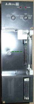
Input and output points: 1024 points.
In
MITSUBISHI
CPU unit
A2ASCPU-S1
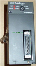
I/O points: 512.
Processing speed: sec/
MITSUBISHI
Motion CPU module
Q172DCPU-S1

Upgraded version.
Control axis: maximum
MITSUBISHI
Motion CPU module
Q173DCPU-S1

Upgraded version.
Control axis: maximum