Brand Sort:
MITSUBISHI
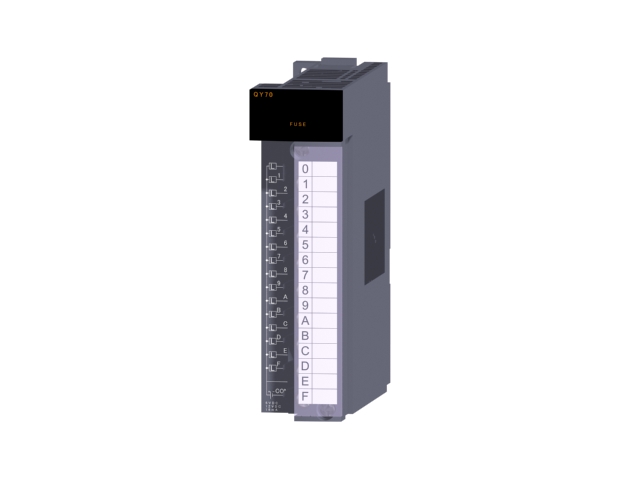
QY70 Market price | QY70 Introduction
- Brand: MITSUBISHI
- Country: JAPAN
- Name: CMOS TTL output module
- Model: QY70
- Price: U.S.$ 364.41
MITSUBISHI QY70
A pack of 10.
Applicable models:
AJ65VBTS - - - type.
AJ65VBTCE - - - type.
AJ65VBTCU - - - type.
AJ65ABTP - - - type.
AJ65VBCU- - type. Total input and output points: 8 points.
Output points: 8 points.
Output type: transistor output.
FX2N extension module.
The expansion module is an input and output expansion device of the power supply from the basic unit or the expansion unit,
Can choose the relay or crystal output models, to 8 points for the unit to connect QY70
Can be extended to FX3GA/FX3G, FX3GE, FX3GC, as well as FX3U, FX3UC series,
When connecting to FX3UC or FX3GC, you need FX2NC-CNV-IF or FX3UC-1PS-5V.
The number of connection points depends on the basic unit and the expansion unit.
FX Series in the compact body built in superior performance, and strive to operate simple.
In addition, rich options can meet the various needs of customers.
In the virtual factory will be rich in the function of a part of the introduction.
It is easy to control the analog quantity of the application.
Can be extended to all models in the FX series analog devices.
Function extension board, special adapter without programming can be used for communication. Accessories for 5.7 inch models.
Applicable models: GT15, GT11. SI/QSI/H-PCF/ wide range H-PCF fiber optic cable.
Double loop.
PC inter network (management station / station) / remote I/O network (remote control station).
External power supply function.
How to choose MITSUBISHI PLC.
MITSUBISHI PLC options include the choice of MITSUBISHI PLC models, capacity, I/O module, power, etc..
MITSUBISHI PLC distribution I/O points and design MITSUBISHI PLC peripheral hardware circuit
Draw the I/O point of the PLC and the input / output device connection diagram or the corresponding table,
This part also can be carried out in second steps.
Design PLC peripheral hardware circuit.
Draw the electrical wiring diagram of the other parts of the system,
Including the main circuit and the control circuit does not enter the PLC, etc..
The electrical schematic diagram of the system composed of I/O PLC connection diagram and PLC peripheral electrical circuit diagram.
So far the system''s hardware electrical circuit has been determined.
QY70 Operation manual/Instructions/Model selection sample download link: /searchDownload.html?Search=QY70&select=5
...more relevant model market price >>>>
Related products
MITSUBISHI
Thyristor output module
QY22
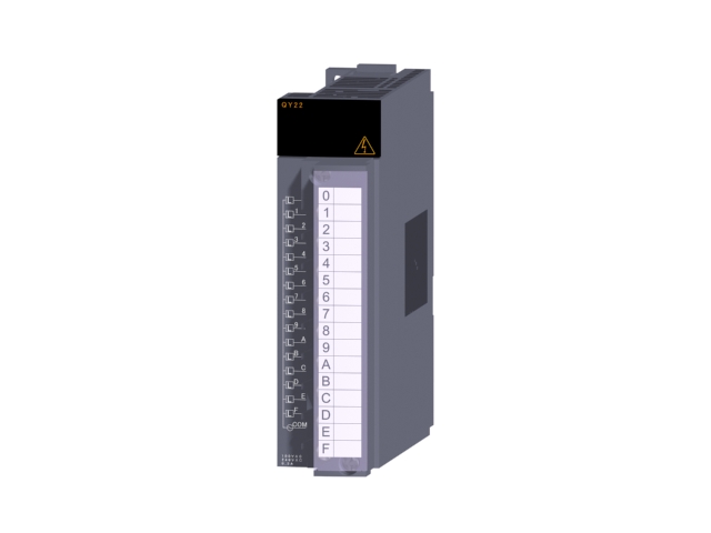
Output points: 16 points.
Minimum load v
MITSUBISHI
Relay output module
QY13L
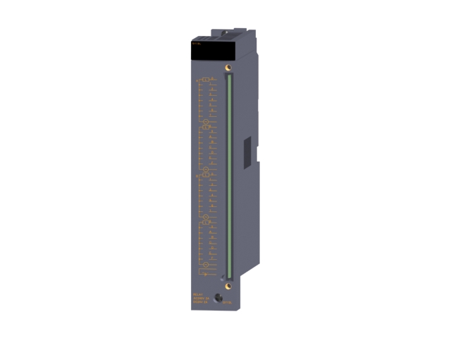
Relay output: 32.
Rated current and volt
MITSUBISHI
Positioning module
AD70
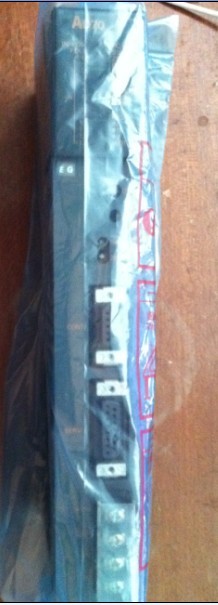
1 axes.
Control unit: pulse.
Determine t
MITSUBISHI
Relay output module (spring clip terminal)
QY10-TS
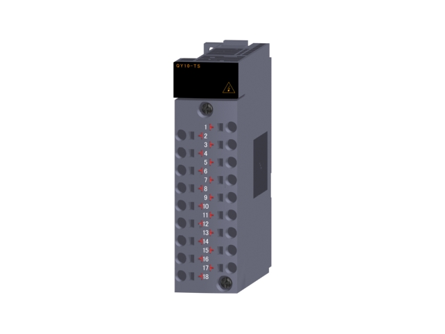
Output points: 16 points.
Output voltage

