Brand Sort:
MITSUBISHI
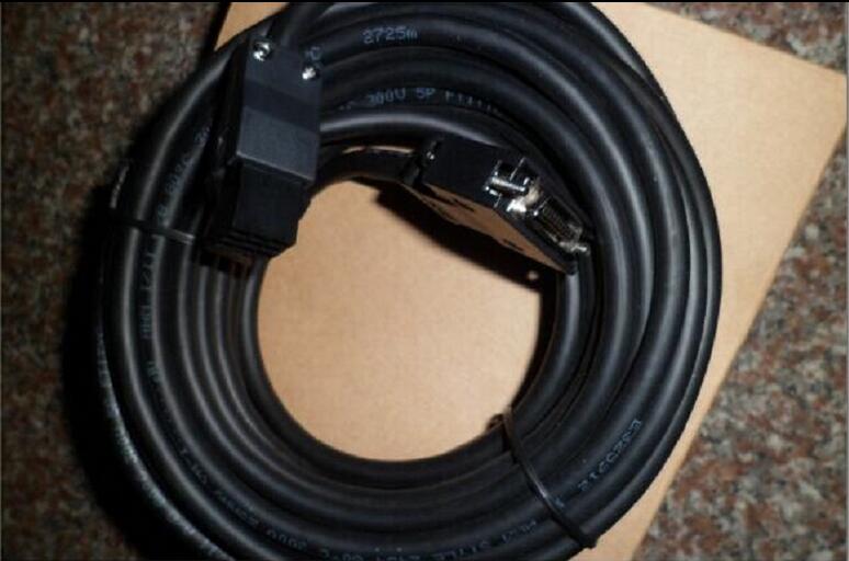
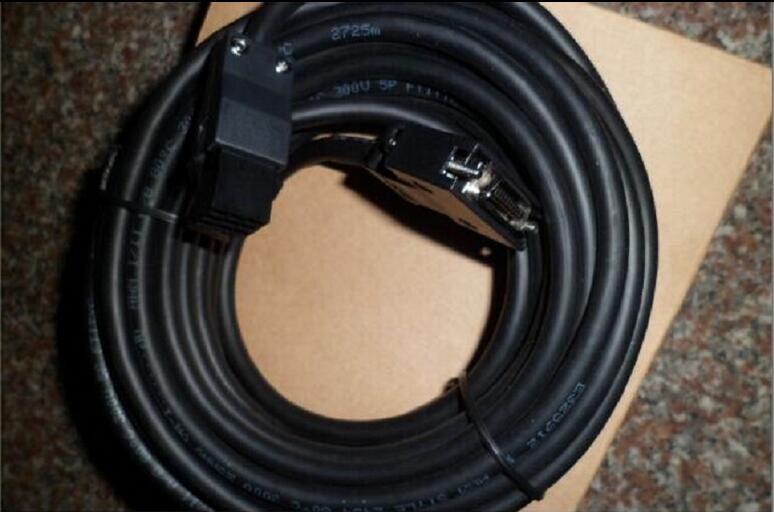
MR-CPCATCBL3M Market price | MR-CPCATCBL3M Introduction
- Brand: MITSUBISHI
- Country: JAPAN
- Name: Personal computer communication cable
- Model: MR-CPCATCBL3M
- Price: U.S.$ 177.97
MITSUBISHI MR-CPCATCBL3M
Type: general purpose AC servo amplifier MR-E series.
Rated output: 0.1kw.
Interface type: analog input interface.
KH003 special mark for Super MR-E.
Servo amplifier terminals are used to reduce the required wiring time.
The connector is located in front of the servo amplifier, which is convenient for cable connection.
The gain adjustment can be easily carried out by the real-time automatic tuning function MR-CPCATCBL3M
Wide use.
Machining equipment and machine tool feed.
Used for food, packaging equipment and feeding device.
For textile machinery, etc..
Can improve the performance of equipment. Function: RS-232C communication.
Adapter for connecting the left extension function of the CPU module.
CPU module can be connected to the left side up to 6 units. The length of the line: 2M.
IP level: IP65.
Relay type.
Bending life: standard.
Connector kit for motor electromagnetic brake.
Cable for electromagnetic brake, for HF-KP/HF-MP series (motor shaft with side extraction). Type: HC-PQ type.
Output power: 0.2kw.
Rated speed: 3000r/min.
Electromagnetic brake: there.
Key axis: D type shaft.
Motor aspects: the material, structure and processing technology of the servo motor is much higher than that of AC motor,
That is when the driver output current, voltage, frequency change is fast power supply,
The servo motor can change according to the change of the response of the power supply,
Response characteristics and anti overload capacity is much higher than the AC motor drive,
Motor aspects of the serious differences between the two are fundamentally different performance.
That is not the inverter output can not change so fast power signal,
But the motor itself can not react,
So in the frequency of the internal algorithm set to protect the motor to do the corresponding overload.
Of course, even without the ability to set the output of the inverter is limited,
Some of the excellent performance of the inverter can be directly driven servo motor. 8 slots.
Power supply unit.
QnAS series unit installation.
High speed access.
I/O points is an important indicator of PLC.
Reasonable selection of I/O points can not only satisfy the control requirements of the system,
And the total investment of the system is the lowest.
The input and output points and types of PLC should be determined according to the analog quantity and switch quantity of the controlled object,
Generally an input / output element to take up an input / output point.
Taking into account the future adjustment and expansion,
In general should be estimated on the total number of points plus the amount of spare 20%~30%.
When the programmer input programinto the user program memory,
Then CPU according to the function of the system (the system program memory to explain the compiler),
Translate the user program into PLC internally recognized by the user to compile the program.
Relay output interface circuit of PLC
Working process: when the internal circuit output digital signal 1,
There is a current flowing through, the relay coil has a current, and then the normally open contact is closed,
Provide load current and voltage.
When the internal circuit outputs a digital signal 0, there is no current flowing through it,
The relay coil does not have a current, and the normally open contact is broken off,
A current or voltage that is disconnected from the load.
It is through the output interface circuit to the internal digital circuit into a signal to make the load action or not action.
MR-CPCATCBL3M Operation manual/Instructions/Model selection sample download link: /searchDownload.html?Search=MR-CPCATCBL3M&select=5
...more relevant model market price >>>>
Related products
MITSUBISHI
Personal computer communication cable
MR-JRPCATCBL3M

Cale length: 3m.
for MR-J2S- / CP 1
MITSUBISHI
Personal computer communication cable
MR-CPCATCBL3M

Cale length: 3m.
For MR-J2S-11KA 4 MR
