Brand Sort:
MITSUBISHI
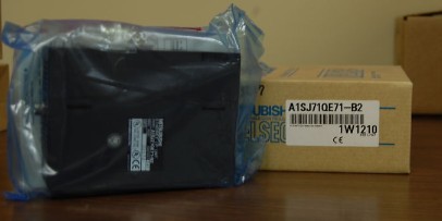
A1SJ71QE71-B2 Market price | A1SJ71QE71-B2 Introduction
- Brand: MITSUBISHI
- Country: JAPAN
- Name: Network module
- Model: A1SJ71QE71-B2
- Price: U.S.$ 169.49
MITSUBISHI A1SJ71QE71-B2
MELSECNET/10, MELSECNET/H coaxial.
Input voltage: DC24V.
How to choose MITSUBISHI PLC.
MITSUBISHI PLC options include the choice of MITSUBISHI PLC models, capacity, I/O module, power, etc..
MITSUBISHI PLC distribution I/O points and design MITSUBISHI PLC peripheral hardware circuit
Draw the I/O point of the PLC and the input / output device connection diagram or the corresponding table,
This part also can be carried out in second steps A1SJ71QE71-B2
Design PLC peripheral hardware circuit.
Draw the electrical wiring diagram of the other parts of the system,
Including the main circuit and the control circuit does not enter the PLC, etc..
The electrical schematic diagram of the system composed of I/O PLC connection diagram and PLC peripheral electrical circuit diagram.
So far the system''s hardware electrical circuit has been determined. Input type: DC input, positive public end / negative public end.
Input points: 4 points.
Input response time: 0.5ms below /1.5ms.
Rated input voltage / current: DC24V/4mA.
External connection: 2 wire.
Spring clip terminal.
Do not need to re tighten, suitable for wire specifications for 0.3~1.5MM square.
Terminal block is 2 piece structure.
An input module shared by the common terminal of the positive and negative.
The 8 point of the output module is appended to the source type.
Can be installed along the 6 direction. Input points: 16 points.
Output points: 16 points.
Output form: transistor.
Connected programmable logic controller: FX1NC, FX2NC, FX3UC.
FX2NC expansion module can be directly connected to the FX1NC, FX2NC, PLC FX3UC on the expansion of the input and output.
Do not need to connect the cable and so on, therefore can carry on the compact expansion. 1 axis servo amplifier.
MITSUBISHI general AC servo amplifier MELSERVO-J4 series.
Rated output: 1.0kw.
Interface: General purpose.
Power supply: three phase AC200V.
Servo amplifier supporting universal interface.
Servo amplifier for universal interface.
Speed / torque control of position control and analog voltage command can be carried out by using pulse train command.
Support Max instruction pulse frequency 4 Mpulses/s.
2 low frequency vibration can be suppressed at the same time by supporting the seismic algorithm of 3 inertial equipment.
Configurator2 MR to achieve convenient adjustment.
Effectively restrain the low frequency aftershock effect produced by the front end of the boom or the main body of the device 100Hz.
Can effectively shorten the time to control the stability of the aftershock.
In the XY design of trajectory control, improve the accuracy of arc track.
At the same time, it can effectively control the phenomenon of quadrant protrusion caused by the rotation direction of the servo motor, which is caused by friction and twisting.
A1SJ71QE71-B2 Operation manual/Instructions/Model selection sample download link: /searchDownload.html?Search=A1SJ71QE71-B2&select=5
...more relevant model market price >>>>
Related products
MITSUBISHI
Melsecnet interface module
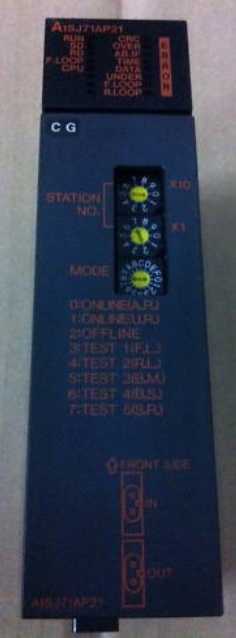
A1SJ71AP21

PLC station distance: 1Km.
Cale type: Q
MITSUBISHI
Network module
A1SJ71QE71N-T

10BASE-T.
MITSUBISHI
Master control module
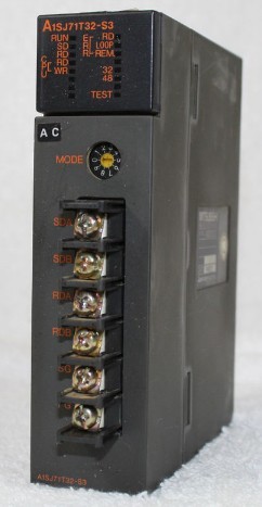
A1SJ71T32-S3

Cale type: twisted pair.
A1SJ71PT32-S3
MITSUBISHI
Ethernet module
A1SJ71E71N3-T

10BASE-T.
The structured text programmin

