Brand Sort:
MITSUBISHI
A3VTS Market price | A3VTS Introduction
- Brand: MITSUBISHI
- Country: JAPAN
- Name: parts
- Model: A3VTS
- Price: 0 >
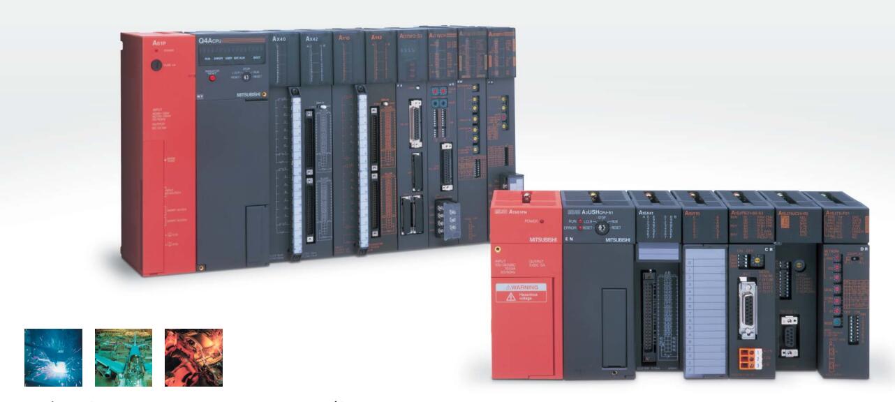
MITSUBISHI A3VTS
Input voltage: AC100-240V.
Rated output: DC5V, 5A.
The power supply module is connected with the external power supply,
AnS programmable controller to provide the required DC5V,
They are inserted in the slot of the special power supply component on the base board,
The output of the DC5V is powered by the power supply on the substrate to the component.
The input voltage of the component is related to the selected model A3VTS
A1S61PN/62PN has Deng generation A1S61P/A1S62P, A1S61PEU/A1S62PEU. Motor series: low inertia, low power.
Rated output power: 0.2kw.
Rated speed: 3000r/min.
Whether to bring the brakes: with.
Shaft end: key shaft (open slot).
Protection level: IP55 does not include the shaft part and the connector.
Features: low inertia is particularly suitable for high speed motor (6000 or 12000 RPM / min) of general industrial machinery.
Application example 1: drive belt drive, robot.
Application example 2: assembly machine, sewing machine, X-Y working table.
Application example 3: food manufacturing machinery, semiconductor manufacturing equipment, knitting machine and embroidery machine.
High resolution encoder 131072p/rev (17 bit).
The encoder with high resolution ensures excellent performance and stability at low speed.
All motor dimensions are the same as before and all are compatible with the wiring. 3C-2V/5C-2V coaxial cable.
Single bus.
Remote I/O network (remote control station).
How to choose MITSUBISHI PLC.
MITSUBISHI PLC options include the choice of MITSUBISHI PLC models, capacity, I/O module, power, etc..
MITSUBISHI PLC distribution I/O points and design MITSUBISHI PLC peripheral hardware circuit
Draw the I/O point of the PLC and the input / output device connection diagram or the corresponding table,
This part also can be carried out in second steps.
Design PLC peripheral hardware circuit.
Draw the electrical wiring diagram of the other parts of the system,
Including the main circuit and the control circuit does not enter the PLC, etc..
The electrical schematic diagram of the system composed of I/O PLC connection diagram and PLC peripheral electrical circuit diagram.
So far the system''s hardware electrical circuit has been determined.
A3VTS Operation manual/Instructions/Model selection sample download link: /searchDownload.html?Search=A3VTS&select=5
...more relevant model market price >>>>
Related products
MITSUBISHI
floor
A32RB

Two slots in one side.
Power supply unit
MITSUBISHI
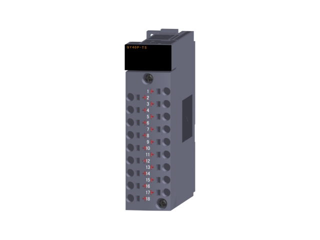
Transistor output module (spring clip terminal)
QY40P-TS

Output points: 16 points.
Output voltage
MITSUBISHI
CPU unit
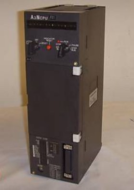
A3NCPUP21

Input and output points: 2048 points.
In
MITSUBISHI
Multiple system module
A3VTU

Module for A3VTS multiplex system.
MITSU

