 LK Automation Limited
Download Sort:
MITSUBISHI
MITSUBISHI AX50-S1 Manual AX50-S1 User's Manual
Product model: AX50-S1
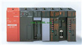
Name: I/O Module
Brand: MITSUBISHI
Sort: User's Manual
File language: English
Download link: MITSUBISHI AX50-S1 User's Manual
Axis of control: 1.
A1SD70 is a kind of voltage output type single axis positioning control module,
Equipped with a servo motor can form a closed loop control system of precise positioning.
Its fastest positioning speed up to 400Kpps, the location of the 32 bit binary number (with a symbol bit).
Positioning units according to the specific application settings, such as the number of pulses, millimeters, inches or degrees AX50-S1 Manual AX50-S1 User's Manual AX50-S1 Input and output points: 480 points.
Program capacity: 7K step.
Basic command processing speed: 4.4 ~ 5.6us.
Power supply: input DC5V output 2A DC24V/.
Modular: PLC is the basic components of a separate module.
Medium and large PLC used this way. Easy maintenance.
User program storage capacity: it is a measure of how much the user application can store the number of indicators AX50-S1 Manual AX50-S1 User's Manual.
Usually in words or K words as units. 16 bit binary number is a word,
Every 1024 words are 1K words. PLC to store instructions and data in words.
General logical operation instructions each account for 1 words. Timer / counter,
Shift instruction accounted for 2 words. Data operation instructions for 2~4 AX50-S1 Manual AX50-S1 User's Manual.
Relay output interface circuit of PLC
Working process: when the internal circuit output digital signal 1,
There is a current flowing through, the relay coil has a current, and then the normally open contact is closed,
Provide load current and voltage.
When the internal circuit outputs a digital signal 0, there is no current flowing through it,
The relay coil does not have a current, and the normally open contact is broken off,
A current or voltage that is disconnected from the load.
It is through the output interface circuit to the internal digital circuit into a signal to make the load action or not action. G1-50/125 fiber optic cable.
Double loop.
PC inter network (management station / station) / remote I/O network (remote control station).
How to choose MITSUBISHI PLC.
MITSUBISHI PLC options include the choice of MITSUBISHI PLC models, capacity, I/O module, power, etc..
MITSUBISHI PLC distribution I/O points and design MITSUBISHI PLC peripheral hardware circuit
Draw the I/O point of the PLC and the input / output device connection diagram or the corresponding table,
This part also can be carried out in second steps.
Design PLC peripheral hardware ccircuit AX50-S1 Manual AX50-S1 User's Manual.
Draw the electrical wiring diagram of the other parts of the system,
Including the main circuit and the control circuit does not enter the PLC, etc..
The electrical schematic diagram of the system compoosed of I/O PLC connection diagram and PLC peripheral electrical circuit diagram AX50-S1 Manual AX50-S1 User's Manual.
So far the system''s hardware electrical circuit has been determined.
Related products
MITSUBISHI
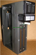
Temperature control module
A1S64TCRTBW-S1
Numer of channels: 4 channels
Sensing m
MITSUBISHI
CPU component
A2SHCPU-S1
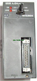
I/O control method: refresh mode or dire
MITSUBISHI
Memory card interface module
AD59-S1
Memory card interface AD59-MEF, parall