 LK Automation Limited
Download Sort:
MITSUBISHI
MITSUBISHI A2SCPU-S1 Dedicated Instructions Manual A2SCPU-S1 Programming Manual
Product model: A2SCPU-S1
Name: PLC
Brand: MITSUBISHI
Sort: Dedicated Instructions Programming Manual
File language: English
Download link: MITSUBISHI A2SCPU-S1 Programming Manual
QnA/ACPU bus connection.
1 joint.
Applicable models: A985 (-V) /975/970/960GOT. Source type output module (standard type).Cable length: 10.6 meters.
Small CPU long distance connecting cable.
For QnAS/AnSCPU/ motion control and GOT connection.
For connection between A7GT-CNB and GOT.
Combination A8GT-EXCNB and A8GT-C_BS A2SCPU-S1 Dedicated Instructions Manual A2SCPU-S1 Programming Manual. D-STN color / monochrome LCD man-machine interface to replace the backlight A2SCPU-S1
Applicable model: A970GOT-SB_/LB_. Input type: DC input, positive common end.
Input points: 16 points.
Enter the response time: 1.5ms the following.
Rated input voltage / current: DC24V/5mA.
External connection: 3 wire.
Sensor connector type (E-CON type).
Using industry standard E-CON type.
Simple wiring through sensor connector A2SCPU-S1 Dedicated Instructions Manual A2SCPU-S1 Programming Manual.
When installing the module can choose to use the DIN guide rail or screw mounting.
3 wire sensor input. 2 slots.
Can be installed in the power supply unit for A series units installed QnA/.
When the programmer input programinto the user program memory,
Then CPU according to the function of the system (the system program memory to explain the compiler),
Translate the user program into PLC internally recognized by the user to compile the program A2SCPU-S1 Dedicated Instructions Manual A2SCPU-S1 Programming Manual.
Relay output interface circuit of PLC
Working process: when the internal circuit output digital signal 1,
There is a current flowing through, the relay coil has a current, and then the normally open contact is closed,
Provide load current and voltage.
When the internal circuit outputs a digital signal 0, there is no current flowing through it,
The relay coil does not have a current, and the normally open contact is broken off,
A current or voltage that is disconnected from the load.
It is through the output interface circuit to the internal digital circuit into a signal to make the load action or not action.
I/O points is an important indicator of PLC.
Reasonable selection of I/O points can not only satisfy the control requirements of the system,
And the total investment of the system is the lowest.
The input and output points and types of PLC should be determined according to the analog quantity and switch quantity of tthe controlled object,
Generally an input / output element to take up an input / output point A2SCPU-S1 Dedicated Instructions Manual A2SCPU-S1 Programming Manual.
Taking into account the future adjustment and expansion,
In general should be estimaated on the total number of points plus the amount of spare 20%~30% A2SCPU-S1 Dedicated Instructions Manual A2SCPU-S1 Programming Manual.
The following describes the centralized control system I/O points of the estimate.
Related products
MITSUBISHI
CPU unit
A2SCPU
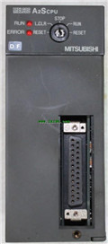
Program memory capacity 14K.
Input and o
MITSUBISHI
CPU unit
A2ASCPU-S1
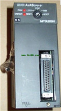
I/O points: 512.
Processing speed: sec/
MITSUBISHI
Motion CPU module
Q172DCPU-S1
Upgraded version.
Control axis: maximum
MITSUBISHI
Moving CPU unit
A73CPU-S1
Multi axis positioning controller.
Progr