 LK Automation Limited
Download Sort:
MITSUBISHI
MITSUBISHI AJ71QE71N-T Manual AJ71QE71N-T User's Manual
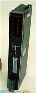
Product model: AJ71QE71N-T
Name: Ethernet Interface Module
Brand: MITSUBISHI
Sort: User's Manual
File language: English
Download link: MITSUBISHI AJ71QE71N-T User's Manual
Input voltage range: AC100 ~ 120V.
Output voltage: DC24V.
Output current: 0.6A.
Relay output interface circuit of PLC
Working process: when the internal circuit output digital signal 1,
There is a current flowing through, the relay coil has a current, and then the normally open contact is closed,
Provide load current and voltage AJ71QE71N-T Manual AJ71QE71N-T User's Manual.
When the internal circuit outputs a digital signal 0, there is no current flowing through it,
The relay coil does not have a current, and the normally open contact is broken off,
A current or voltage that is disconnected from the load AJ71QE71N-T
It is through the output interface circuit to the internal digital circuit into a signal to make the load action or not action.
I/O points is an important indicator of PLC AJ71QE71N-T Manual AJ71QE71N-T User's Manual.
Reasonable selection of I/O points can not only satisfy the control requirements of the system,
And the total investment of the system is the lowest.
The input and output points and types of PLC should be determined according to the analog quantity and switch quantity of the controlled object,
Generally an input / output element to take up an input / output point AJ71QE71N-T Manual AJ71QE71N-T User's Manual.
Taking into account the future adjustment and expansion,
In general should be estimated on the total number of points plus the amount of spare 20%~30%.
The following describes the centralized control system I/O points of the estimate. DC input points: 2 points.
Input voltage and current: 7mA, DC24V.
Input response time: 10ms.
2 point /1 a public side.
Positive / negative sharing.
Output points: 2 points.
Output voltage and current: DC24V/AC240V, 2A/1 point, 4A/1 common end.
Output response time: 2ms.
2 point /1 a public side.
Output form: relay.
16 point terminal station.
MITSUBISHI PLC protection and chain procedures.
Protection and chain is an indispensable part of the program, must be carefully considered.
It can avoid the control logic confusion caused by illegal operations.
MITSUBISHI PLC initialization procedure. After MITSUBISHI PLC on power, the general need to do some of the initial operation,
In order to start making necessary preparations, to avoid the wrong operation of the system.
The main contents of the initialization program are: to some data area, counter and so on,
Data needed to restore some of the data area,
Set or reset some relays,
For some initial state display, etc..
MITSUBISHI PLC program simulation debugging
The basiic idea of program simulation debugging is,
In order to facilitate the form of simulation to generate the actual state of the scene,
Create the necessary environmental conditions for the operation of thee program AJ71QE71N-T Manual AJ71QE71N-T User's Manual AJ71QE71N-T Manual AJ71QE71N-T User's Manual.
Depending on the way the field signals are generated,
The simulation debugging has two forms of hardware simulation and software simulation.
Related products
MITSUBISHI
SI/QSI fiber optic cable module
AJ71QLP21
SI/QSI/H-PCF/ wide range H-PCF fier opt
MITSUBISHI
Ethernet module
AJ71QE71N-B2
10BASE2.
For Q mode.
Control layer /MELS
MITSUBISHI
Coaxial cable module
AJ71QBR11

3C-2V/5C-2V coaxial cale.
Single us.
P
MITSUBISHI
Serial communication module
AJ71QC24
RS-232 1 channel, RS-422/485 1 channel.