 LK Automation Limited
Download Sort:
MITSUBISHI
MITSUBISHI AJ71QE71N3-T Manual AJ71QE71N3-T User's Manual
Product model: AJ71QE71N3-T
Name: Ethernet Interface Module
Brand: MITSUBISHI
Sort: User's Manual
File language: English
Download link: MITSUBISHI AJ71QE71N3-T User's Manual
Input and output points: 2048 points.
Input / output data points: 2048 points.
Program capacity: 30K.
Basic command processing speed (LD command) s:1.0.
Each scanning process. Focus on the input signal sampling. Focus on the output signal to refresh.
Input refresh process. When the input port is closed,
Program in the implementation phase, the input end of a new state, the new state can not be read AJ71QE71N3-T Manual AJ71QE71N3-T User's Manual AJ71QE71N3-T
Only when the program is scanned, the new state is read.
A scan cycle is divided into the input sample, the program execution, the output refresh.
The contents of the component image register are changed with the change of the execution of the program.
The length of the scan cycle is determined by the three AJ71QE71N3-T Manual AJ71QE71N3-T User's Manual.
CPU the speed of executing instructions.
Time of instruction.
Instruction count.
Due to the adoption of centralized sampling.
Centralized output mode.
There exist input / output hysteresis phenomena, i.e., the input / output response delay.
User program storage capacity: it is a measure of how much the user application can store the number of indicators.
Usually in words or K words as units AJ71QE71N3-T Manual AJ71QE71N3-T User's Manual. 16 bit binary number is a word,
Every 1024 words are 1K words. PLC to store instructions and data in words.
General logical operation instructions each account for 1 words. Timer / counter,
Shift instruction accounted for 2 words. Data operation instructions for 2~4. 3C-2V/5C-2V coaxial cable.
Double loop.
PC inter network (management station / common station) / remote I/O network (remote control station).
How to choose MITSUBISHI PLC.
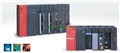
MITSUBISHI PLC options include the choice of MITSUBISHI PLC models, capacity, I/O module, power, etc..
MITSUBISHI PLC distribution I/O points and design MITSUBISHI PLC peripheral hardware circuit
Draw the I/O point of the PLC and the input / output device connection diagram or the corresponding table,
This part also can be carried out in second steps.
Design PLC peripheral hardware circuit.
Drraw the electrical wiring diagram of the other parts of the system,
Including the main circuit and the control circuit does not enter the PLC, etc AJ71QE71N3-T Manual AJ71QE71N3-T User's Manual. .
The electrical schematic diagram of the system compoosed of I/O PLC connection diagram and PLC peripheral electrical circuit diagram AJ71QE71N3-T Manual AJ71QE71N3-T User's Manual.
So far the system''s hardware electrical circuit has been determined.
Input / output data points: 2048 points.
Program capacity: 30K.
Basic command processing speed (LD command) s:1.0.
Each scanning process. Focus on the input signal sampling. Focus on the output signal to refresh.
Input refresh process. When the input port is closed,
Program in the implementation phase, the input end of a new state, the new state can not be read AJ71QE71N3-T Manual AJ71QE71N3-T User's Manual AJ71QE71N3-T
Only when the program is scanned, the new state is read.
A scan cycle is divided into the input sample, the program execution, the output refresh.
The contents of the component image register are changed with the change of the execution of the program.
The length of the scan cycle is determined by the three AJ71QE71N3-T Manual AJ71QE71N3-T User's Manual.
CPU the speed of executing instructions.
Time of instruction.
Instruction count.
Due to the adoption of centralized sampling.
Centralized output mode.
There exist input / output hysteresis phenomena, i.e., the input / output response delay.
User program storage capacity: it is a measure of how much the user application can store the number of indicators.
Usually in words or K words as units AJ71QE71N3-T Manual AJ71QE71N3-T User's Manual. 16 bit binary number is a word,
Every 1024 words are 1K words. PLC to store instructions and data in words.
General logical operation instructions each account for 1 words. Timer / counter,
Shift instruction accounted for 2 words. Data operation instructions for 2~4. 3C-2V/5C-2V coaxial cable.
Double loop.
PC inter network (management station / common station) / remote I/O network (remote control station).
How to choose MITSUBISHI PLC.
MITSUBISHI PLC options include the choice of MITSUBISHI PLC models, capacity, I/O module, power, etc..
MITSUBISHI PLC distribution I/O points and design MITSUBISHI PLC peripheral hardware circuit
Draw the I/O point of the PLC and the input / output device connection diagram or the corresponding table,
This part also can be carried out in second steps.
Design PLC peripheral hardware circuit.
Drraw the electrical wiring diagram of the other parts of the system,
Including the main circuit and the control circuit does not enter the PLC, etc AJ71QE71N3-T Manual AJ71QE71N3-T User's Manual. .
The electrical schematic diagram of the system compoosed of I/O PLC connection diagram and PLC peripheral electrical circuit diagram AJ71QE71N3-T Manual AJ71QE71N3-T User's Manual.
So far the system''s hardware electrical circuit has been determined.
Related products
MITSUBISHI
Ethernet module
AJ71QE71-B5

Ethernet network module 10BASE5
Control
MITSUBISHI
Ethernet module
AJ71QE71N-B2
10BASE2.
For Q mode.
Control layer /MELS
MITSUBISHI
Network module
AJ71E71N3-T
10BASE-T.
When communicating in the PLC
MITSUBISHI
Network module
AJ71QE71N3-T

10BASE-T.
For Q mode.
When communicating