 LK Automation Limited
Download Sort:
MITSUBISHI
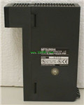
MITSUBISHI A1SJ71UC24-R2-S2 Manual A1SJ71UC24-R2-S2 User's Manual
Product model: A1SJ71UC24-R2-S2
Name: Communication Module
Brand: MITSUBISHI
Sort: User's Manual
File language: English
Download link: MITSUBISHI A1SJ71UC24-R2-S2 User's Manual
Input type: DC input, positive common end.
Input points: 8 points.
Enter the response time: 10ms the following.
Rated input voltage / current: DC24V/7mA.
Output form: transistor output, leakage type.
Output points: 8 points.
OFF leakage current: 0.1mA.
Output protection function: No.
Rated load voltage / current: DC12V/DC24V/0 A1SJ71UC24-R2-S2 Manual A1SJ71UC24-R2-S2 User's Manual. 5A.
External connection: 1 line /1 line type A1SJ71UC24-R2-S2
Type of input and output terminal.
Using 2 pieces of structure of the terminal units, maintenance can be maintained in the same line under the condition of the replacement module. MELSECNET/MINI (-S3) data link system, A2C system transfer converter.
Twisted pair cable - plastic optical fiber cable.
MITSUBISHI PLC protection and chain procedures A1SJ71UC24-R2-S2 Manual A1SJ71UC24-R2-S2 User's Manual.
Protection and chain is an indispensable part of the program, must be carefully considered.
It can avoid the control logic confusion caused by illegal operations.
MITSUBISHI PLC initialization procedure. After MITSUBISHI PLC on power, the general need to do some of the initial operation,
In order to start making necessary preparations, to avoid the wrong operation of the system A1SJ71UC24-R2-S2 Manual A1SJ71UC24-R2-S2 User's Manual.
The main contents of the initialization program are: to some data area, counter and so on,
Data needed to restore some of the data area,
Set or reset some relays,
For some initial state display, etc..
MITSUBISHI PLC program simulation debugging
The basic idea of program simulation debugging is,
In order to facilitate the form of simulation to generate the actual state of the scene,
Create the necessary environmental conditions for the operation of the program.
Depending on the way the field signals are generated,
The simulation debugging has two forms of hardware simulation and software simulation. Output points: 16 points.
Voltage: DC24V/AC240V, 2A/1 point, 16A/ all points.
OFF leakage current: 0.1mA.
Output type: relay output.
Response time: 12ms.
All points of independence.
38 point terminal station.
With the surge absorber.
CE certification.
The number of I/O thyristor DC motor control required tube DC motor speed control system is the main form of DC speed regulation,
The thyristor rectifier unit is used to supply power to the DC motor.
PLC control of the DC drive system, the input of the PLC in addition to the main signal outside the signal,
We need to consider the switching signal, the fault signal transmission device, brake signal and fan fault signal.
The output of the PLC mainly consider the speed command signal positive 1~3 level, 1~3 level, allowing reverse switching signal and brake open signal etc..
In general, a reversible DC drive system controlled by PLC is approximately 12 input points and 8 output points,
An irreversible DC drive system requires 9 inputs and 6 output points.
MITSUBISHI PLC is the main product in the production of MITSUBISHI motor in Dalian.
It uses a kind of programmable memory for its internal storage procedures,
Execute logic operation, sequence control, timing, counting and arithmetic operations, user oriented instruction,
And through digital or analog input / output control of various types of machinery or production process.
Control solenoid valve required I/O points by the action principle of the solenoid valve can be known,
A single coil solenoid valve with PLC control to 2 input and 1 output,
A double coil solenoid valve requires 3 inputs and 2 outputs,
A button needs an input; a light sensitive switch needs 4 or 2 inputs,
A signal lamp needs 1 output, band switch,
Several bands are required for several inputs,
In general, a variety of position switches are required to take up 2 input points A1SJ71UC24-R2-S2 Manual A1SJ71UC24-R2-S2 User's Manual A1SJ71UC24-R2-S2 Manual A1SJ71UC24-R2-S2 User's Manual.
Related products
MITSUBISHI
Computer communication module
A1SJ71UC24-PRF
Interface: RS232C.
Transmission distance
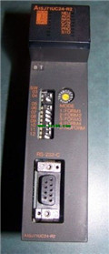
MITSUBISHI
MODBUS interface module
A1SJ71UC24-R2-S2
Data format: ASCII.
Data its: 7.
A1SJ71
MITSUBISHI
Computer communication module
A1SJ71UC24-R2
Interface: RS232C.
Transmission distance
MITSUBISHI
Computer communication module
A1SJ71UC24-R4
Interface: RS422/485
Transmission distan