LK Automation Limited
Download Sort:
MITSUBISHI
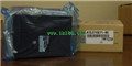
MITSUBISHI A1SJ71UC24-R4 Manual A1SJ71UC24-R4 User's Manual
Product model: A1SJ71UC24-R4
Name: Computer Link Module
Brand: MITSUBISHI
Sort: User's Manual
File language: English
Download link: MITSUBISHI A1SJ71UC24-R4 User's Manual
Series Name: A956GOT.
Size: 6 inches.
Resolution: 320 * 240.
Display device: STN monochrome display.
Display color: monochrome (white and black).
Power supply: DC24V.
Memory card: 1M.
The external model design model of creating the system function is mainly to consider the data structure, the overall structure and the process description of the software,
The interface design is usually only used as accessories, only on the user''s situation (including age, gender, mental status, education level, personality, ethnic background and etc A1SJ71UC24-R4 Manual A1SJ71UC24-R4 User's Manual A1SJ71UC24-R4 ) to understand, to design an effective user interface;
According to the user model of the future system of the end user (for short),
In the end, it is consistent with the system image (external characteristic) of the system after the system is realized,
Users can be satisfied with the system and be able to use it effectively;
When the user model is established, the information given by the system should be considered,
System mapping must accurately reflect the syntax and semantic information of the system A1SJ71UC24-R4 Manual A1SJ71UC24-R4 User's Manual.
In short, only to understand the user, to understand the task in order to design a good man-machine interface A1SJ71UC24-R4 Manual A1SJ71UC24-R4 User's Manual. 2 channels.
200/10kpps.
Count input signal: DC5/12/24V.
External input: DC5/12/24V.
Compare output: transistor DC12/24V, 0.5A/1 point, 2A/1 common.
20 point terminal station.
Structured text language is a programming language that describes a program with a structured description of the text.
It is a programming language similar to a high level language. In large and medium
Structured text is often used to describe the relationship between the various variables in the control system based on the PLC system.
Mainly used for other programming languages more difficult to achieve the user program.
Sequential function flow chart language is designed to satisfy the sequential logic control.
The process of sequential process action is divided into steps and transformation conditions,
According to the transfer condition, the control system is distributed in the function flow sequence,
Step by step according to the sequence of actions.
Each step represents a control function, represented by the box.
In the box, the ladder logic is used to complete the task of the corresponding control function.
This programming language makes the program structure clear and easy to read and maintain,
Greatly reduce the programming workload, shorten the programming and debugging time.
Used in the system of the size of the school, procedures for more complex occasions.
Sequence function flow chart programming language features: to function as the main line, in accordance with the functional flow of the order of distribution, cleear, easy to understand the user program,
Avoid the defect of ladder diagram or other languages,
At the same time, the use of ladder language to avoid the use of ladder programming,
Due to the compllicated mechanical interlock, the structure of the user program is complex and difficult to understand,
User program scan time is also greatly reduced A1SJ71UC24-R4 Manual A1SJ71UC24-R4 User's Manual A1SJ71UC24-R4 Manual A1SJ71UC24-R4 User's Manual.
Related products
MITSUBISHI
Ethernet module
A1SJ71QE71N-B5

10BASE5.
Q mode.
MITSUBISHI PLC is the m
MITSUBISHI
Computer communication module
A1SJ71UC24-R4
Interface: RS422/485
Transmission distan