 LK Automation Limited
Download Sort:
MITSUBISHI
MITSUBISHI AJ71UC24-S2 Manual AJ71UC24-S2 User's Manual
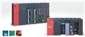
Product model: AJ71UC24-S2
Name: Communication Module
Brand: MITSUBISHI
Sort: User's Manual
File language: English
Download link: MITSUBISHI AJ71UC24-S2 User's Manual
Input and output points: 480 points.
Program capacity: 7K step.
Basic command processing speed: 4.4 ~ 5.6us.
Power supply: input DAC100 ~ 120/200 ~ 240V/ output 2A DC24V, 0.5A DC5V.
Coaxial data communication line function.
Modular: PLC is the basic components of a separate module.
Medium and large PLC used this way AJ71UC24-S2 Manual AJ71UC24-S2 User's Manual. Easy maintenance.
Relay output interface circuit of PLC
Working process: when the internal circuit output digital signal 1,
There is a current flowing through, the relay coil has a current, and then the normally open contact is closed,
Provide load current and voltage AJ71UC24-S2
When the internal circuit outputs a digital signal 0, there is no current flowing through it,
The relay coil does not have a current, and the normally open contact is broken off,
A current or voltage that is disconnected from the load AJ71UC24-S2 Manual AJ71UC24-S2 User's Manual.
It is through the output interface circuit to the internal digital circuit into a signal to make the load action or not action.
User program storage capacity: it is a measure of how much the user application can store the number of indicators.
Usually in words or K words as units AJ71UC24-S2 Manual AJ71UC24-S2 User's Manual. 16 bit binary number is a word,
Every 1024 words are 1K words. PLC to store instructions and data in words.
General logical operation instructions each account for 1 words. Timer / counter,
Shift instruction accounted for 2 words. Data operation instructions for 2~4. Cable 1.2m for the expansion of the floor, the expansion of a floor for every 1 units.RS-232:1 channel, RS-422:1 channel.
BASIC program mode (A3MCPU corresponding): BASIC console interface to use.
Sequential program mode (program controller CPU correspondence): non sequential computer connection interface and use.
How to choose MITSUBISHI PLC.
MITSUBISHI PLC options include the choice of MITSUBISHI PLC models, capacity, I/O module, power, etc..
MITSUBISHI PLC distribution I/O points and design MITSUBISHI PLC peripheral hardware circuit
Draw the I/O point of the PLC and the input / output device connection diagram or the corresponding table,
This part also can be carried out in second steps.
Design PLC peripheral hardware circuit.
Draw the electrical wiring diagram of the other parts of the system,
Including the main circuit and the control circuit does not enter the PLC, etc AJ71UC24-S2 Manual AJ71UC24-S2 User's Manual. .
The electrical schematic diagram of the system compoosed of I/O PLC connection diagram and PLC peripheral electrical circuit diagram AJ71UC24-S2 Manual AJ71UC24-S2 User's Manual.
So far the system''s hardware electrical circuit has been determined.
Related products
MITSUBISHI
Computer communication module
AJ71UC24
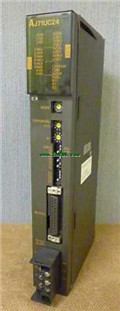
RS-232 1 channel, RS-422/485 1 channel.
MITSUBISHI
CPU unit
A0J2CPU-DC24-S2

Input and output points: 480 points.
Pro