 LK Automation Limited
Download Sort:
MITSUBISHI
MITSUBISHI A1SJ71PB93D Manual A1SJ71PB93D User's Manual
Product model: A1SJ71PB93D
Name: PROFIBUS-DP Slave Module
Brand: MITSUBISHI
Sort: User's Manual
File language: English
Download link: MITSUBISHI A1SJ71PB93D User's Manual
A7HGP/A6GPP-CPU connection.
Length: 30m. Axis of control: 1.
A1SD75 series components show the MITSUBISHI in the manufacture and design of CNC, frequency converter,
Integrated technical experience in servo system and PLC.
These components have a wealth of features that are sufficient to meet the highest requirements in the application of positioning control A1SJ71PB93D Manual A1SJ71PB93D User's Manual A1SJ71PB93D
A1SD75M, SCC net compatible controller, SSC network is the MITSUBISHI servo system control network.
In this network, the MR-H-13, MR-J-B, and MR-J2 servo amplifiers can be connected to a controller via a network system,
The connection is replaced by a pulse sequence and a voltage signal. Output type: transistor output, drain type.
Output points: 32 points A1SJ71PB93D Manual A1SJ71PB93D User's Manual.
OFF leakage current: 0.1mA.
Output protection function: No.
Rated load voltage / current: DC12V/DC24V/0.5A.
External connection: 2 wire.
Spring clip terminal.
Do not need to be tightened further or locked with screws, which can reduce the working hours of wiring.
Using 2 pieces of structure of the terminal units, maintenance can be maintained in the same line under the condition of the replacement module A1SJ71PB93D Manual A1SJ71PB93D User's Manual.
When installing the module can choose to use the DIN guide rail or screw mounting.
Can be used for the 3 wire sensor input wiring. 3C-2V/5C-2V coaxial cable.
Double loop.
PC inter network (management station / common station) / remote I/O network (remote control station).
How to choose MITSUBISHI PLC.
MITSUBISHI PLC options include the choice of MITSUBISHI PLC models, capacity, I/O module, power, etc..
MITSUBISHI PLC distribution I/O points and design MITSUBISHI PLC peripheral hardware circuit
Draw the I/O point of the PLC and the input / output device connection diagram or the corresponding table,
This part also can be carried out in second steps.
Design PLC peripheral hardware circuit.
Draw the electrical wiring diagram of the other parts of the system,
Including the main circuit and the control circuit does not enter the PLC, etc A1SJ71PB93D Manual A1SJ71PB93D User's Manual. .
The electrical schematic diagram of the system compoosed of I/O PLC connection diagram and PLC peripheral electrical circuit diagram A1SJ71PB93D Manual A1SJ71PB93D User's Manual.
So far the system''s hardware electrical circuit has been determined.
Related products
MITSUBISHI
Melsecnet interface module
A1SJ71AP21GE
PLC station distance: 2Km.
Cale type: G
MITSUBISHI
Serial communication module
A1SJ71QC24N
RS-232 1 channel.
RS-422/485 1 channel.
MITSUBISHI
Network module
A1SJ71QE71N-T
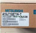
10BASE-T.