 LK Automation Limited
Download Sort:
MITSUBISHI
MITSUBISHI A1SD75P3-S3 Hardware Manual A1SD75P3-S3 User's Manual
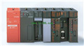
Product model: A1SD75P3-S3
Name: Positioning Module
Brand: MITSUBISHI
Sort: Hardware User's Manual
File language: English
Download link: MITSUBISHI A1SD75P3-S3 User's Manual
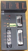
16 channels.
Input: DC-10 ~ 10V, DC-20 ~ 20mA.
38 point terminal station.
Analog quantity I/P multiplexing unit (isolation channel).
Detailed analysis of the process and work characteristics of the controlled object,
To understand the coordination between the controlled object machine, electricity and liquid,
The control requirements of the controlled object for MITSUBISHI PLC control system are put forward,
Determine the control program, to develop a design task book A1SD75P3-S3 Hardware Manual A1SD75P3-S3 User's Manual A1SD75P3-S3
How to determine the input / output device of MITSUBISHI plc.
According to the control requirements of the system,
All input devices and output devices required for the determination of the system,
To determine the input / output device related to the MITSUBISHI PLC,
To determine the I/O PLC points A1SD75P3-S3 Hardware Manual A1SD75P3-S3 User's Manual. Series Name: A956GOT.
Size: 6 inches.
Resolution: 320 * 240.
Display equipment: high brightness TFT color display.
Display color: 256 color.
Power supply: DC24V.
Memory card: 3M.
The external model design model of creating the system function is mainly to consider the data structure, the overall structure and the process description of the software,
The interface design is usually only used as accessories, only on the user''s situation (including age, gender, mental status, education level, personality, ethnic background and etc A1SD75P3-S3 Hardware Manual A1SD75P3-S3 User's Manual. ) to understand, to design an effective user interface;
According to the user model of the future system of the end user (for short),
In the end, it is consistent with the system image (external characteristic) of the system after the system is realized,
Users can be satisfied with the system and be able to use it effectively;
When the user model is established, the information given by the system should be considered,
System mapping must accurately reflect the syntax and semantic information of the system.
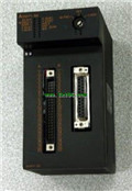
In short, only to understand the user, to understand the task in order to design a good man-machine interface. 5 slots.
Can be installed in the power supply unit for A series units installed QnA/.
Relay output interface circuit of PLC
Working process: when the internal circuit output digital signal 1,
There is a current flowing through, the relay coil has a current, and then the normally open contact is closed,
Provide load current and voltage.
When the internal circuit outputs a digital signal 0, there is no current flowing through it,
The relay coil does not have a current, and the normally open contact is broken off,
A current or voltage that is disconnected from the load.
It is through the output interface circuit to the internal digital circuit into a signal to make the load action or not action.
I/O points is an important indicator of PLC.
Reasonable selection of I/O points can not only satisfy the control requirements of the system,
And the total investment of the system is the lowest.
The input and output points and types of PLC should be determined according to the analog quantity and switcch quantity of the controlled object,
Generally an input / output element to take up an input / output point A1SD75P3-S3 Hardware Manual A1SD75P3-S3 User's Manual.
Taking into account the future adjustment and expansion,
In general should be estimaated on the total number of points plus the amount of spare 20%~30% A1SD75P3-S3 Hardware Manual A1SD75P3-S3 User's Manual.
The following describes the centralized control system I/O points of the estimate.
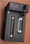
Input: DC-10 ~ 10V, DC-20 ~ 20mA.
38 point terminal station.
Analog quantity I/P multiplexing unit (isolation channel).
Detailed analysis of the process and work characteristics of the controlled object,
To understand the coordination between the controlled object machine, electricity and liquid,
The control requirements of the controlled object for MITSUBISHI PLC control system are put forward,
Determine the control program, to develop a design task book A1SD75P3-S3 Hardware Manual A1SD75P3-S3 User's Manual A1SD75P3-S3
How to determine the input / output device of MITSUBISHI plc.
According to the control requirements of the system,
All input devices and output devices required for the determination of the system,
To determine the input / output device related to the MITSUBISHI PLC,
To determine the I/O PLC points A1SD75P3-S3 Hardware Manual A1SD75P3-S3 User's Manual. Series Name: A956GOT.
Size: 6 inches.
Resolution: 320 * 240.
Display equipment: high brightness TFT color display.
Display color: 256 color.
Power supply: DC24V.
Memory card: 3M.
The external model design model of creating the system function is mainly to consider the data structure, the overall structure and the process description of the software,
The interface design is usually only used as accessories, only on the user''s situation (including age, gender, mental status, education level, personality, ethnic background and etc A1SD75P3-S3 Hardware Manual A1SD75P3-S3 User's Manual. ) to understand, to design an effective user interface;
According to the user model of the future system of the end user (for short),
In the end, it is consistent with the system image (external characteristic) of the system after the system is realized,
Users can be satisfied with the system and be able to use it effectively;
When the user model is established, the information given by the system should be considered,
System mapping must accurately reflect the syntax and semantic information of the system.
In short, only to understand the user, to understand the task in order to design a good man-machine interface. 5 slots.
Can be installed in the power supply unit for A series units installed QnA/.
Relay output interface circuit of PLC
Working process: when the internal circuit output digital signal 1,
There is a current flowing through, the relay coil has a current, and then the normally open contact is closed,
Provide load current and voltage.
When the internal circuit outputs a digital signal 0, there is no current flowing through it,
The relay coil does not have a current, and the normally open contact is broken off,
A current or voltage that is disconnected from the load.
It is through the output interface circuit to the internal digital circuit into a signal to make the load action or not action.
I/O points is an important indicator of PLC.
Reasonable selection of I/O points can not only satisfy the control requirements of the system,
And the total investment of the system is the lowest.
The input and output points and types of PLC should be determined according to the analog quantity and switcch quantity of the controlled object,
Generally an input / output element to take up an input / output point A1SD75P3-S3 Hardware Manual A1SD75P3-S3 User's Manual.
Taking into account the future adjustment and expansion,
In general should be estimaated on the total number of points plus the amount of spare 20%~30% A1SD75P3-S3 Hardware Manual A1SD75P3-S3 User's Manual.
The following describes the centralized control system I/O points of the estimate.
Related products
MITSUBISHI
Voltage output positioning control module
A1SD70
Axis of control: 1.
A1SD70 is a kind of
MITSUBISHI
Pulse output positioning control module
A1SD71-S2
Axis of control: 2.
A1SD71-S2 is a linea
MITSUBISHI
Positioning module
A1SD71-S7
2 axes.
2 axis linear interpolation.
Con