 LK Automation Limited
Brand:
MITSUBISHI
A1SD75P1 | MITSUBISHI Positioning module A1SD75P1
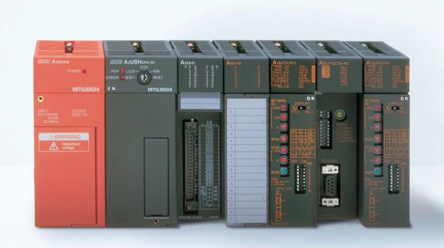
MITSUBISHI A1SD75P1 Manual And Instructions
A1SD75P1 datasheetPDF datasheet
A1SD75P1 User's Manual
A1SD75P1 HardwareUser's Manual
MITSUBISHI A1SD75P1 Product information and technical parameters:
Brand: MITSUBISHI
Name: Positioning module
Model: A1SD75P1
...More relevant models >>>>
A1SD75P1 datasheetPDF datasheet
A1SD75P1 User's Manual
A1SD75P1 HardwareUser's Manual
MITSUBISHI A1SD75P1 Product information and technical parameters:
Brand: MITSUBISHI
Name: Positioning module
Model: A1SD75P1
5 slots.
Installation of the power unit can not be used for AnS QnAS/ series units installed.
The popularization and application of PLC programming has been developed rapidly in our country,
It has been widely used in all kinds of mechanical equipment and production process of electrical control devices,
All walks of life have emerged a large number of application of PLC transformation of the results of the equipment MITSUBISHI A1SD75P1 A1SD75P1
Understand the working principle of PLC, have the ability to design, debug and maintain the PLC control system,
Has become the basic requirements of modern industry for electrical technicians and engineering students.
PLC user program is designed according to the control system of the process control requirements,
PLC programming language through the preparation of specifications, in accordance with the actual needs of the use of the function to design MITSUBISHI A1SD75P1.
As long as the user can master some kind of standard programming language,
To be able to use PLC in the control system,
To achieve a variety of automatic control functions. 8 slots; requires 1 AnS series PLC power modules;
Used to install large AnS series PLC module MITSUBISHI A1SD75P1.
Base plate of AnS series PLC.
QA1S series PLC 8 slot main substrate.
AnS series of modules can be installed. Input and output points: 512 points.
Input / output data points: 8192 points.
Program capacity: 14K.
Basic command processing speed (LD command) s:0.2.
Internal storage RAM memory capacity: 64K
PLC in the program execution stage: according to the order of the user program order to store the order of each instruction,
After the corresponding operation and processing, the reesult is written to the output status register,
The contents of the output status register are changed with the execution of the program A1SD75P1.
Output refresh phase: when all instructions are executed,
The output status register is sent to the ouutput latch in the output refresh stage,
And through a certain way (relay, transistor or transistor) output, drive the corresponding output equipment A1SD75P1. .
...More relevant models >>>>