 LK Automation Limited
Download Sort:
MITSUBISHI
MITSUBISHI A1NCPUP21 Fundamentals Manual A1NCPUP21 Programming Manual
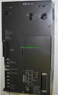
Product model: A1NCPUP21
Name: PLC
Brand: MITSUBISHI
Sort: Fundamentals Programming Manual
File language: English
Download link: MITSUBISHI A1NCPUP21 Programming Manual
Program memory capacity: 8k.
Input / output points: maximum 256 points.
A scan cycle of PLC must pass through three stages: input sampling, program execution and output refresh.
PLC in the input sampling phase: first of all, in order to scan the sequence of all existing input latches in the input terminal of the state or input data read,
And write it into the corresponding input status register,
Refresh the input, then close the input port, enter the program execution stage A1NCPUP21 Fundamentals Manual A1NCPUP21 Programming Manual A1NCPUP21 2 slots.
Can be installed in the power supply unit for A series units installed QnA/.
When the programmer input programinto the user program memory,
Then CPU according to the function of the system (the system program memory to explain the compiler),
Translate the user program into PLC internally recognized by the user to compile the program A1NCPUP21 Fundamentals Manual A1NCPUP21 Programming Manual.
Relay output interface circuit of PLC
Working process: when the internal circuit output digital signal 1,
There is a current flowing through, the relay coil has a current, and then the normally open contact is closed,
Provide load current and voltage.
When the internal circuit outputs a digital signal 0, there is no current flowing through it,
The relay coil does not have a current, and the normally open contact is broken off,
A current or voltage that is disconnected from the load A1NCPUP21 Fundamentals Manual A1NCPUP21 Programming Manual.
It is through the output interface circuit to the internal digital circuit into a signal to make the load action or not action.
I/O points is an important indicator of PLC.
Reasonable selection of I/O points can not only satisfy the control requirements of the system,
And the total investment of the system is the lowest.
The input and output points and types of PLC should be determined according to the analog quantity and switch quaantity of the controlled object,
Generally an input / output element to take up an input / output point A1NCPUP21 Fundamentals Manual A1NCPUP21 Programming Manual.
Taking into account the future adjustment and expansion,
In general should be estimaated on the total number of points plus the amount of spare 20%~30% A1NCPUP21 Fundamentals Manual A1NCPUP21 Programming Manual.
The following describes the centralized control system I/O points of the estimate.
Related products
MITSUBISHI
CPU unit
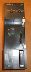
A0J2HCPUP21

Input and output points: 480 points.
Inp
MITSUBISHI
CPU unit
A1NCPUP21
Input and output points: 256 points.
Inp
MITSUBISHI
CPU unit
A2ACPUP21
Input and output points: 512 points.
Inp
MITSUBISHI
CPU unit
A2NCPUP21
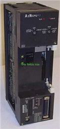
Input and output points: 512 points.
Inp