 LK Automation Limited
Brand:
MITSUBISHI
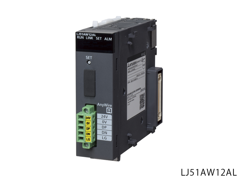
LJ51AW12AL | MITSUBISHI AnyWireASLINK master module LJ51AW12AL
MITSUBISHI LJ51AW12AL Manual And Instructions
LJ51AW12AL datasheetPDF datasheet
MITSUBISHI LJ51AW12AL Product information and technical parameters:
Brand: MITSUBISHI
Name: AnyWireASLINK master module
Model: LJ51AW12AL
AnyWireASLINK master station.
Transmission distance: the longest 200m.
Data input and output: up to 512 points.
Connect up to 128 units.
Enter 256 points, 256 points out of the output.
Connecting the input and output of the sensor to the programmable controller.
Ultra small sensor can be freely configured to control the input and output of 512 points.
In addition, the sensor can be supplied with a AnyWireASLINK transmission line (2 lines) by means of communication,
So as to facilitate additional sensor.
And can also be through the engineering software Works2 GX batch management sensor disconnection detection and from the station module settings, etc.,
Can significantly reduce the engineering hours.
Basic composition.
AnyWireASLINKAnyWireASLINK can be selected according to the load current of 2 wire or 4 wire from the station module.
In addition to the 2 wire type, the local power supply can be connected with the 4 wire type mixed use.
2 wire type.
The load current is less than that of the hour, by using the non isolated 2 wire type from the station module,
Easy connection without using local power supply.
4 wire type
By using isolated 4 wire type from the station module, the local power supply can be used,
Can support the use of more current load.
...More relevant models >>>>
LJ51AW12AL datasheetPDF datasheet
MITSUBISHI LJ51AW12AL Product information and technical parameters:
Brand: MITSUBISHI
Name: AnyWireASLINK master module
Model: LJ51AW12AL
AnyWireASLINK master station.
Transmission distance: the longest 200m.
Data input and output: up to 512 points.
Connect up to 128 units.
Enter 256 points, 256 points out of the output.
Connecting the input and output of the sensor to the programmable controller.
Ultra small sensor can be freely configured to control the input and output of 512 points.
In addition, the sensor can be supplied with a AnyWireASLINK transmission line (2 lines) by means of communication,
So as to facilitate additional sensor.
And can also be through the engineering software Works2 GX batch management sensor disconnection detection and from the station module settings, etc.,
Can significantly reduce the engineering hours.
Basic composition.
AnyWireASLINKAnyWireASLINK can be selected according to the load current of 2 wire or 4 wire from the station module.
In addition to the 2 wire type, the local power supply can be connected with the 4 wire type mixed use.
2 wire type.
The load current is less than that of the hour, by using the non isolated 2 wire type from the station module,
Easy connection without using local power supply.
4 wire type
By using isolated 4 wire type from the station module, the local power supply can be used,
Can support the use of more current load.
Open collector output.
Axis of control: 4.
Maximum output pulse: pulse/s 200k.
Location data: 600 data / axis.
Max link distance: 2m.
With the parameter setting, the synchronization control can be easily realized. Do not need to write complex procedures.
Start / stop with synchronous control of the shaft MITSUBISHI LJ51AW12AL.
Synchronous control of the axis and the positioning of the axis can coexist LJ51AW12AL
Through the clutch, the movement of the main shaft can be transferred to the output shaft.
Simple implementation of synchronization control.
Cam control is more simple
Cam data can easily create a variety of patterns.
Can be simple to achieve the gear, shaft, transmission, cam and other mechanical mechanisms to replace the software synchronization control MITSUBISHI LJ51AW12AL.
It is not subject to the limitation of the concept of the electronic cam control so far, and can use the cam with high degree of freedom.
The stroke, speed, acceleration and beat can be confirmed on the graph, and the setting is carried out at the same time.
Can also be through the cam data thumbnail display, easy to confirm the cam data has been created MITSUBISHI LJ51AW12AL.
Can import and export the cam data in CSV format. Output points: 16 points.
Output form: source type.
Rated output voltage: DC12 ~ 24V.
Max load current: 0.5A/1 point.
Protection function: have.
Common way: 16 point / public end.
Input / output occupied points: 16 points (I/O distribution: output 16 points).
External wiring connection: 18 point terminal.
The switch input and output module is a device which can collect the input / output of the switch signal,
Digital I/O modules are often called.
The switch signal is collected to the computer or the computer to send the relevant instructions through the RS-485 bus to control the switch of the switch,
Can also be carried out through the RS-485 bus communication,
Remote control switch.
Communication protocol is a standard Modbus protocol or custom protocol. Can be used as a screw relay terminal.Number of input channels: 8ch.
Input current: DC0 ~ 20mA.
Conversion speed: 1ms/ch.
Resolution: 1/8000.
By shifting the function easily when the system starts to fine tune the movement function.
Shift the set value to (shift to) the function of the digital output value.
If you change the conversion value, the value is reflected in real time to the value of the scale (numeric value),
Can easily complete the fine-tuning of the system startup.
Extended detection method based on usage
Anomaly detection and extension of input signal
The detection method of the abnormal detection function of the input signal can be extended to detect the abnormal detection function of the input signal which is outside the range of the set range LJ51AW12AL.
For the detection of the lower limit or the upper limit of the input signal abnormality, or when the detection of the broken line is performed.
Enter rannge extension
Range of scalable input range LJ51AW12AL.
Combined with the abnormal detection function of the input signal, the broken line can be easily detected.
...More relevant models >>>>