 LK Automation Limited
Brand:
MITSUBISHI
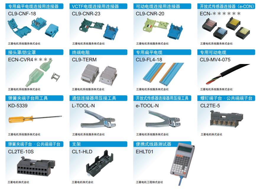
CL9-CNR-20 | MITSUBISHI Connector for connecting movable cable CL9-CNR-20
MITSUBISHI CL9-CNR-20 Manual And Instructions
CL9-CNR-20 datasheetPDF datasheet
MITSUBISHI CL9-CNR-20 Product information and technical parameters:
Brand: MITSUBISHI
Name: Connector for connecting movable cable
Model: CL9-CNR-20
No introduction
...More relevant models >>>>
CL9-CNR-20 datasheetPDF datasheet
MITSUBISHI CL9-CNR-20 Product information and technical parameters:
Brand: MITSUBISHI
Name: Connector for connecting movable cable
Model: CL9-CNR-20
No introduction
Output type: transistor output, drain type.
Output points: 8 points.
OFF leakage current: 0.1mA.
Output protection function.
Rated load voltage / current: DC24V/DC24V/0.1A.
External connection: 2 wire.
Sensor connector type (E-CON type).
Using industry standard E-CON type.
Simple wiring through sensor connector MITSUBISHI CL9-CNR-20.
When installing the module can choose to use the DIN guide rail or screw mounting CL9-CNR-20
3 wire sensor input. Input type: DC input, positive common end.
Input points: 8 points.
Enter the response time: 10ms the following.
Rated input voltage / current: DC24V/7mA.
Output form: transistor output, leakage type.
Output points: 8 points.
OFF leakage current: 0.1mA.
Output protection function: No MITSUBISHI CL9-CNR-20.
Rated load voltage / current: DC12V/DC24V/0.5A.
External connection: 1 line /1 line type.
Type of input and output terminal.
Using 2 pieces of structure of the terminal units, maintenance can be maintained in the same line under the condition of the replacement module. Number of channels: RS422, 1 channel
.
Configuration of master / local station,
In addition to the other site network with different CC-Link in addition to the main station and the remote station configuration can also be the main station and the local station configuration MITSUBISHI CL9-CNR-20.
A local PLC can communicate with the master station PLC and other remote workstations.
MITSUBISHI PLC online debugging.
On-line debugging is the process that will through the simulation debugging to further carry on the on-line unification to adjust.
On-line debugging process should be step by step,
From MITSUBISHI PLC only connected to the input device, and then connect the output device, and then connect to the actual load and so on and so on step by step.
If you do not meet the requirements, the hardware and procedures for adjustment.
Usually only need to modify the part of the program can be.
MITSUBISHI PLC hardware implementation
Hardware implementation is mainly for the control cabinet and other hardware design and field construction.
Design control cabinet and the operating table and other parts of tthe electrical wiring diagram and wiring diagram CL9-CNR-20.
Electrical interconnection diagram of each part of the design system.
According to the construction drawings of the site wiring, and carry out a detailed inspection.
Because the program deesign and hardware implementation can be carried out at the same time,
So the design cycle of the MITSUBISHI PLC control system can be greatly reduced CL9-CNR-20.
Output points: 8 points.
OFF leakage current: 0.1mA.
Output protection function.
Rated load voltage / current: DC24V/DC24V/0.1A.
External connection: 2 wire.
Sensor connector type (E-CON type).
Using industry standard E-CON type.
Simple wiring through sensor connector MITSUBISHI CL9-CNR-20.
When installing the module can choose to use the DIN guide rail or screw mounting CL9-CNR-20
3 wire sensor input. Input type: DC input, positive common end.
Input points: 8 points.
Enter the response time: 10ms the following.
Rated input voltage / current: DC24V/7mA.
Output form: transistor output, leakage type.
Output points: 8 points.
OFF leakage current: 0.1mA.
Output protection function: No MITSUBISHI CL9-CNR-20.
Rated load voltage / current: DC12V/DC24V/0.5A.
External connection: 1 line /1 line type.
Type of input and output terminal.
Using 2 pieces of structure of the terminal units, maintenance can be maintained in the same line under the condition of the replacement module. Number of channels: RS422, 1 channel
.
Configuration of master / local station,
In addition to the other site network with different CC-Link in addition to the main station and the remote station configuration can also be the main station and the local station configuration MITSUBISHI CL9-CNR-20.
A local PLC can communicate with the master station PLC and other remote workstations.
MITSUBISHI PLC online debugging.
On-line debugging is the process that will through the simulation debugging to further carry on the on-line unification to adjust.
On-line debugging process should be step by step,
From MITSUBISHI PLC only connected to the input device, and then connect the output device, and then connect to the actual load and so on and so on step by step.
If you do not meet the requirements, the hardware and procedures for adjustment.
Usually only need to modify the part of the program can be.
MITSUBISHI PLC hardware implementation
Hardware implementation is mainly for the control cabinet and other hardware design and field construction.
Design control cabinet and the operating table and other parts of tthe electrical wiring diagram and wiring diagram CL9-CNR-20.
Electrical interconnection diagram of each part of the design system.
According to the construction drawings of the site wiring, and carry out a detailed inspection.
Because the program deesign and hardware implementation can be carried out at the same time,
So the design cycle of the MITSUBISHI PLC control system can be greatly reduced CL9-CNR-20.
...More relevant models >>>>