 LK Automation Limited
Brand:
MITSUBISHI
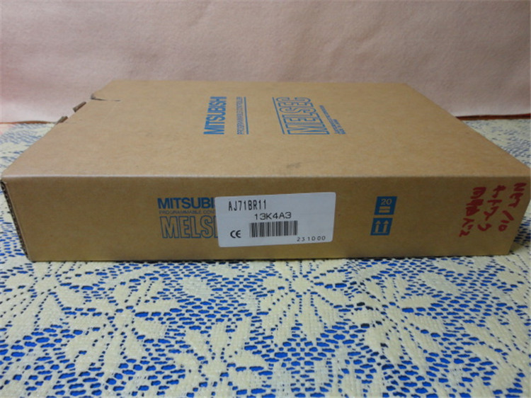
AJ71BR11 | MITSUBISHI Coaxial cable module AJ71BR11
MITSUBISHI AJ71BR11 Manual And Instructions
AJ71BR11 datasheetPDF datasheet
AJ71BR11 Reference Manual
AJ71BR11 PLC to PLC networkReference Manual
AJ71BR11 Reference Manual
AJ71BR11 Reference Manual
MITSUBISHI AJ71BR11 Product information and technical parameters:
Brand: MITSUBISHI
Name: Coaxial cable module
Model: AJ71BR11
3C-2V/5C-2V coaxial cable.
Single bus.
PC inter network (management station / station) / remote I/O network (remote control station).
How to choose MITSUBISHI PLC.
MITSUBISHI PLC options include the choice of MITSUBISHI PLC models, capacity, I/O module, power, etc..
MITSUBISHI PLC distribution I/O points and design MITSUBISHI PLC peripheral hardware circuit
Draw the I/O point of the PLC and the input / output device connection diagram or the corresponding table,
This part also can be carried out in second steps.
Design PLC peripheral hardware circuit.
Draw the electrical wiring diagram of the other parts of the system,
Including the main circuit and the control circuit does not enter the PLC, etc..
The electrical schematic diagram of the system composed of I/O PLC connection diagram and PLC peripheral electrical circuit diagram.
So far the system''s hardware electrical circuit has been determined.
...More relevant models >>>>
AJ71BR11 datasheetPDF datasheet
AJ71BR11 Reference Manual
AJ71BR11 PLC to PLC networkReference Manual
AJ71BR11 Reference Manual
AJ71BR11 Reference Manual
MITSUBISHI AJ71BR11 Product information and technical parameters:
Brand: MITSUBISHI
Name: Coaxial cable module
Model: AJ71BR11
3C-2V/5C-2V coaxial cable.
Single bus.
PC inter network (management station / station) / remote I/O network (remote control station).
How to choose MITSUBISHI PLC.
MITSUBISHI PLC options include the choice of MITSUBISHI PLC models, capacity, I/O module, power, etc..
MITSUBISHI PLC distribution I/O points and design MITSUBISHI PLC peripheral hardware circuit
Draw the I/O point of the PLC and the input / output device connection diagram or the corresponding table,
This part also can be carried out in second steps.
Design PLC peripheral hardware circuit.
Draw the electrical wiring diagram of the other parts of the system,
Including the main circuit and the control circuit does not enter the PLC, etc..
The electrical schematic diagram of the system composed of I/O PLC connection diagram and PLC peripheral electrical circuit diagram.
So far the system''s hardware electrical circuit has been determined.
Input and output points: 480 points.
Program capacity: 7K step.
Basic command processing speed: 4.4 ~ 5.6us.
Power supply: input DAC100 ~ 120/200 ~ 240V/ output 2A DC24V, 0.5A DC5V.
Optical data communication line.
Modular: PLC is the basic components of a separate module.
Medium and large PLC used this way MITSUBISHI AJ71BR11. Easy maintenance.
Relay output interface circuit of PLC
Working process: when the internal circuit output digital signal 1,
There is a current flowing through, the relay coil has a current, and then the normally open contact is closed,
Provide load current and voltage AJ71BR11
When the internal circuit outputs a digital signal 0, there is no current flowing through it,
The relay coil does not have a current, and the normally open contact is broken off,
A current or voltage that is disconnected from the load MITSUBISHI AJ71BR11.
It is through the output interface circuit to the internal digital circuit into a signal to make the load action or not action.
User program storage capacity: it is a measure of how much the user application can store the number of indicators.
Usually in words or K words as units MITSUBISHI AJ71BR11. 16 bit binary number is a word,
Every 1024 words are 1K words. PLC to store instructions and data in words.
General logical operation instructions each account for 1 words. Timer / counter,
Shift instruction accounted for 2 words. Data operation instructions for 2~4. Input points: 16 points.
Voltage: AC200 ~ 240V.
Current: 10mA.
Response time: 25ms.
16 points / a common end..
20 point terminal station.
System program memory for storing system program,
Including management procedures, monitoring procedures, as well as the user program to do the compiler to compile the process of interpretation.
Read only memory. Manufacturers use, content can not be changed, power does not disappear.
PLC selection with the development of PLC technology, more and more types of PLC products,
Function is becoming more and more perfect, and its application is more and more extensive.
Different series of different models of PLC has different performance, applicable occasions also have different emphasis,
Price also has a greater difference. Therefore PLC selection,
Under the premise of meeting the control requirements,
Should consider the best performance to price ratio, a reasonable choice of PLC.
Each scanning process. Focus on the input signal sampling. Focus on the output signal to refresh.
Input refresh process. When the input port is closed,
Program in the implementation phase, the input end of a new state, the new state can not be read.
Only when the program is scanned, the new state is read.
A scan cycle is divided into the input sample, the program execution, the output refresh.
The contents oof the component image register are changed with the change of the execution of the program AJ71BR11.
The length of the scan cycle is determined by the three.
CPU the speed of executing instructions.
Time of instruction.
Instruction count.
Due to thhe adoption of centralized sampling AJ71BR11.
Centralized output mode.
There exist input / output hysteresis phenomena, i.e., the input / output response delay.
...More relevant models >>>>