 LK Automation Limited
Brand:
MITSUBISHI
AC12B | MITSUBISHI Extension cable AC12B
MITSUBISHI AC12B Manual And Instructions
AC12B datasheetPDF datasheet
MITSUBISHI AC12B Product information and technical parameters:
Brand: MITSUBISHI
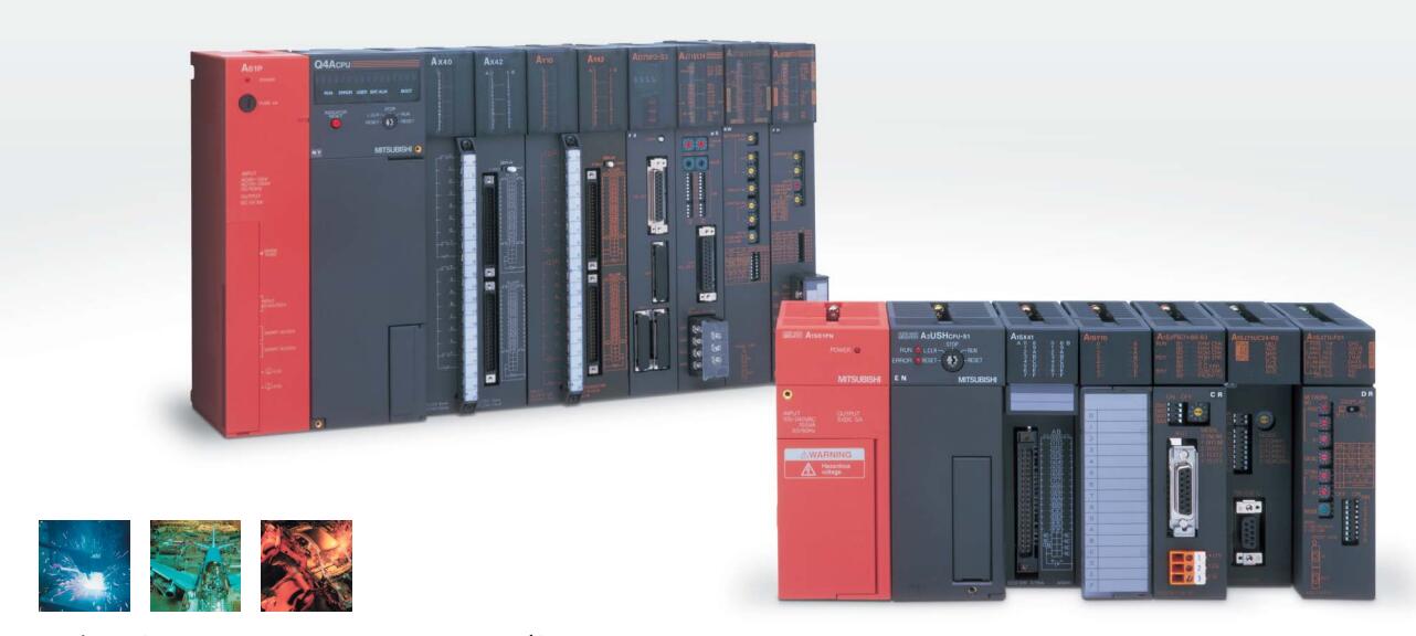
Name: Extension cable
Model: AC12B
Cable 1.2m for the expansion of the floor, the expansion of a floor for every 1 units.
...More relevant models >>>>
AC12B datasheetPDF datasheet
MITSUBISHI AC12B Product information and technical parameters:
Brand: MITSUBISHI
Name: Extension cable
Model: AC12B
Cable 1.2m for the expansion of the floor, the expansion of a floor for every 1 units.
Enter 16 points.
Voltage and current: 14mA DC24V.
Response time: 8ms.
16 point 1 public end, 20 point terminal.
Detailed analysis of the process and work characteristics of the controlled object,
To understand the coordination between the controlled object machine, electricity and liquid,
The control requirements of the controlled object for MITSUBISHI PLC control system are put forward,
Determine the control program, to develop a design task book MITSUBISHI AC12B AC12B
How to determine the input / output device of MITSUBISHI plc.
According to the control requirements of the system,
All input devices and output devices required for the determination of the system,
To determine the input / output device related to the MITSUBISHI PLC,
To determine the I/O PLC points MITSUBISHI AC12B. GI fiber optic cable.
Double circuit.
MELSECNET (II) (remote I/O station).
According to the control requirements of the system, using the appropriate design method to design MITSUBISHI PLC program.
Procedures to meet the requirements of system control as the main line,
Write one by one to achieve the control function or the sub task of the program,
Gradually improve the functions specified by the system MITSUBISHI AC12B.
MITSUBISHI PLC initialization procedure. After MITSUBISHI PLC on power, the general need to do some of the initial operation,
In order to start making necessary preparations, to avoid the wrong operation of the system.
The main contents of the initialization program are: to some data area, counter and so on,
Data needed to restore some of the data area,
Set or reset some relays,
For some initial state display, etc.. A3VTS using the basic unit.
Relay output interface circuit of PLC
Working process: when the internal circuit output digital signal 1,
There is a current flowing through, the relay coil has a current, and then the normally open contact is closed,
Provide load current and voltage.
When the internal circuit outputs a digital signal 0, there is no current flowing through it,
The relay coil does not have a current, and the normally open contact is broken off,
A current or voltage that is disconnected from the load.
It is through the output interface circuit to the internal digital circuit into a signal to make the load action or not action.
When the programmer input programinto the user program memory,
Then CPU according to the function of the system (the system program memory to explain the compiler),
Translate the user program into PLC internally recognized by the user to compile the program.
I/O points is an important indicator of PLC.
Reasonable selection of I/O points can not only satisfy the control requirements of the system,
And the total investment of the system is the lowest.
The input and output points and types of PLC should be deteermined according to the analog quantity and switch quantity of the controlled object,
Generally an input / output element to take up an input / output point AC12B.
Taking into account the future adjustment and expansion,
In general should be estimaated on the total number of points plus the amount of spare 20%~30% AC12B.
The following describes the centralized control system I/O points of the estimate.
...More relevant models >>>>