 LK Automation Limited
Brand:
MITSUBISHI
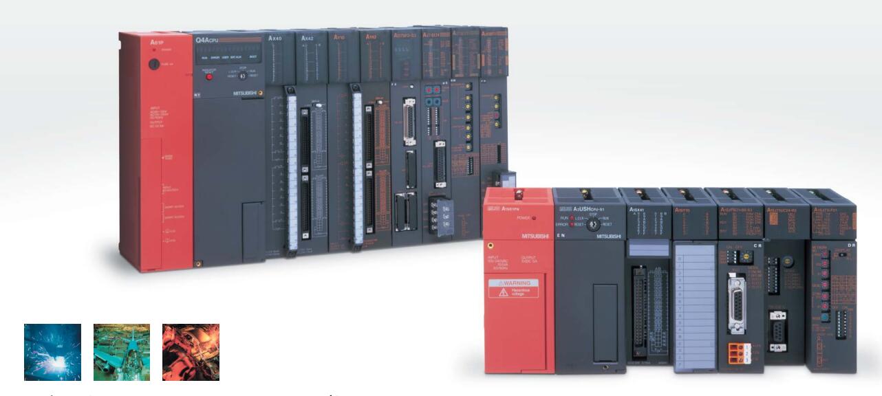
A6BR10-DC | MITSUBISHI MELSECNET/10 repeater module A6BR10-DC
MITSUBISHI A6BR10-DC Manual And Instructions
A6BR10-DC datasheetPDF datasheet
MITSUBISHI A6BR10-DC Product information and technical parameters:
Brand: MITSUBISHI
Name: MELSECNET/10 repeater module
Model: A6BR10-DC
MELSECNET/10, MELSECNET/H coaxial.
Input voltage: DC24V.
How to choose MITSUBISHI PLC.
MITSUBISHI PLC options include the choice of MITSUBISHI PLC models, capacity, I/O module, power, etc..
MITSUBISHI PLC distribution I/O points and design MITSUBISHI PLC peripheral hardware circuit
Draw the I/O point of the PLC and the input / output device connection diagram or the corresponding table,
This part also can be carried out in second steps.
Design PLC peripheral hardware circuit.
Draw the electrical wiring diagram of the other parts of the system,
Including the main circuit and the control circuit does not enter the PLC, etc..
The electrical schematic diagram of the system composed of I/O PLC connection diagram and PLC peripheral electrical circuit diagram.
So far the system''s hardware electrical circuit has been determined.
...More relevant models >>>>
A6BR10-DC datasheetPDF datasheet
MITSUBISHI A6BR10-DC Product information and technical parameters:
Brand: MITSUBISHI
Name: MELSECNET/10 repeater module
Model: A6BR10-DC
MELSECNET/10, MELSECNET/H coaxial.
Input voltage: DC24V.
How to choose MITSUBISHI PLC.
MITSUBISHI PLC options include the choice of MITSUBISHI PLC models, capacity, I/O module, power, etc..
MITSUBISHI PLC distribution I/O points and design MITSUBISHI PLC peripheral hardware circuit
Draw the I/O point of the PLC and the input / output device connection diagram or the corresponding table,
This part also can be carried out in second steps.
Design PLC peripheral hardware circuit.
Draw the electrical wiring diagram of the other parts of the system,
Including the main circuit and the control circuit does not enter the PLC, etc..
The electrical schematic diagram of the system composed of I/O PLC connection diagram and PLC peripheral electrical circuit diagram.
So far the system''s hardware electrical circuit has been determined.
Multi axis positioning controller.
Coaxial data communication line function.
Program capacity: Max 60K step.
Input / output points: 1920 points.
PLC commonly used in memory are EPROM, EEPROM and with lithium battery powered RAM.
General micro and small PLC storage capacity is fixed, between 1~2KB.
How much memory is occupied by a user application is related to many factors,
Such as I/O points, control requirements, computing processing, program structure, etc MITSUBISHI A6BR10-DC A6BR10-DC .
So it can only be roughly estimated before the program is designed. Input and output points: 480 points.
Program capacity: 7K step.
Basic command processing speed: 4.4 ~ 5.6us.
Power supply: input DAC100 ~ 120/200 ~ 240V/ output 2A DC24V, 0 MITSUBISHI A6BR10-DC. 5A DC5V.
Coaxial data communication line function.
Modular: PLC is the basic components of a separate module.
Medium and large PLC used this way. Easy maintenance.
Relay output interface circuit of PLC
Working process: when the internal circuit output digital signal 1,
There is a current flowing through, the relay coil has a current, and then the normally open contact is closed,
Provide load current and voltage MITSUBISHI A6BR10-DC.
When the internal circuit outputs a digital signal 0, there is no current flowing through it,
The relay coil does not have a current, and the normally open contact is broken off,
A current or voltage that is disconnected from the load.
It is through the output interface circuit to the internal digital circuit into a signal to make the load action or not action.
User program storage capacity: it is a measure of how much the user application can store the number of indicators.
Usually in words or K words as units. 16 bit binary number is a word,
Every 1024 words are 1K words. PLC to store instructions and data in words.
General logical operation instructions each account for 1 words. Timer / counter,
Shift instruction accounted for 2 words. Data operation instructions for 2~4. Cable 3M for the expansion of the floor, the expansion of a floor for every 1 units.Input and output points: 1024 points.
Input / output data points: 1024 points.
Program capacity: 14K.
Optical data communication line function (GI cable).
Each scanning process. Focus on the input signal sampling. Focus on the output signal to refresh.
Input refresh process. When the input port is closed,
Program in the implementation phase, the input end of a new state, the new state can not be read.
Only when the program is scanned, the new state is read.
A scan cycle is divided into the input sample, the program execution, the output refresh.
The contents of the component image register are changed with the change of the execution of the program.
The length of the scan cycle is determined by the three.
CPU the speed of executing instructions.
Time of instruction.
Instruction count.
Due to the adoption of centralized sampling.
Centralized output mode.
There exist input / output hysteresis phenomena, i.e., the input / output response delay.
User program storage capacity: itt is a measure of how much the user application can store the number of indicators A6BR10-DC.
Usually in words or K words as units. 16 bit binary number is a word,
Every 1024 words are 1K words. PLC to store instructions and data in words.
General llogical operation instructions each account for 1 words A6BR10-DC. Timer / counter,
Shift instruction accounted for 2 words. Data operation instructions for 2~4.
Coaxial data communication line function.
Program capacity: Max 60K step.
Input / output points: 1920 points.
PLC commonly used in memory are EPROM, EEPROM and with lithium battery powered RAM.
General micro and small PLC storage capacity is fixed, between 1~2KB.
How much memory is occupied by a user application is related to many factors,
Such as I/O points, control requirements, computing processing, program structure, etc MITSUBISHI A6BR10-DC A6BR10-DC .
So it can only be roughly estimated before the program is designed. Input and output points: 480 points.
Program capacity: 7K step.
Basic command processing speed: 4.4 ~ 5.6us.
Power supply: input DAC100 ~ 120/200 ~ 240V/ output 2A DC24V, 0 MITSUBISHI A6BR10-DC. 5A DC5V.
Coaxial data communication line function.
Modular: PLC is the basic components of a separate module.
Medium and large PLC used this way. Easy maintenance.
Relay output interface circuit of PLC
Working process: when the internal circuit output digital signal 1,
There is a current flowing through, the relay coil has a current, and then the normally open contact is closed,
Provide load current and voltage MITSUBISHI A6BR10-DC.
When the internal circuit outputs a digital signal 0, there is no current flowing through it,
The relay coil does not have a current, and the normally open contact is broken off,
A current or voltage that is disconnected from the load.
It is through the output interface circuit to the internal digital circuit into a signal to make the load action or not action.
User program storage capacity: it is a measure of how much the user application can store the number of indicators.
Usually in words or K words as units. 16 bit binary number is a word,
Every 1024 words are 1K words. PLC to store instructions and data in words.
General logical operation instructions each account for 1 words. Timer / counter,
Shift instruction accounted for 2 words. Data operation instructions for 2~4. Cable 3M for the expansion of the floor, the expansion of a floor for every 1 units.Input and output points: 1024 points.
Input / output data points: 1024 points.
Program capacity: 14K.
Optical data communication line function (GI cable).
Each scanning process. Focus on the input signal sampling. Focus on the output signal to refresh.
Input refresh process. When the input port is closed,
Program in the implementation phase, the input end of a new state, the new state can not be read.
Only when the program is scanned, the new state is read.
A scan cycle is divided into the input sample, the program execution, the output refresh.
The contents of the component image register are changed with the change of the execution of the program.
The length of the scan cycle is determined by the three.
CPU the speed of executing instructions.
Time of instruction.
Instruction count.
Due to the adoption of centralized sampling.
Centralized output mode.
There exist input / output hysteresis phenomena, i.e., the input / output response delay.
User program storage capacity: itt is a measure of how much the user application can store the number of indicators A6BR10-DC.
Usually in words or K words as units. 16 bit binary number is a word,
Every 1024 words are 1K words. PLC to store instructions and data in words.
General llogical operation instructions each account for 1 words A6BR10-DC. Timer / counter,
Shift instruction accounted for 2 words. Data operation instructions for 2~4.
...More relevant models >>>>