 LK Automation Limited
Brand:
MITSUBISHI
A32B-S1 | MITSUBISHI floor A32B-S1
MITSUBISHI A32B-S1 Manual And Instructions
A32B-S1 datasheetPDF datasheet
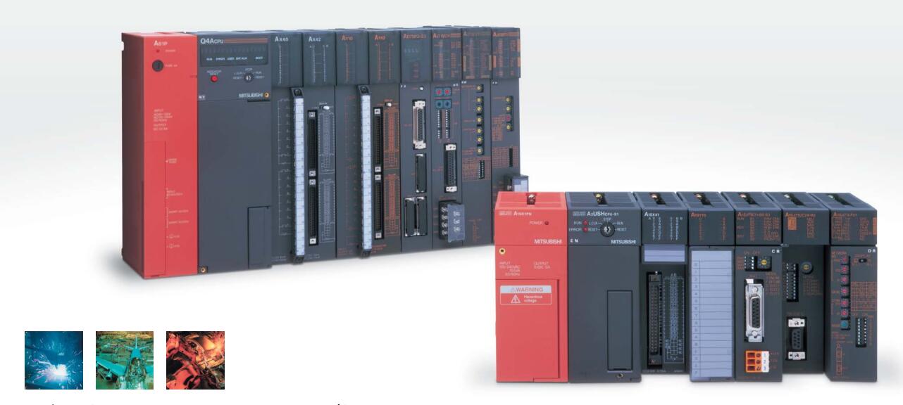
MITSUBISHI A32B-S1 Product information and technical parameters:
Brand: MITSUBISHI
Name: floor
Model: A32B-S1
2 slots.
Can be installed in the power supply unit for A series units installed QnA/.
When the programmer input programinto the user program memory,
Then CPU according to the function of the system (the system program memory to explain the compiler),
Translate the user program into PLC internally recognized by the user to compile the program.
Relay output interface circuit of PLC
Working process: when the internal circuit output digital signal 1,
There is a current flowing through, the relay coil has a current, and then the normally open contact is closed,
Provide load current and voltage.
When the internal circuit outputs a digital signal 0, there is no current flowing through it,
The relay coil does not have a current, and the normally open contact is broken off,
A current or voltage that is disconnected from the load.
It is through the output interface circuit to the internal digital circuit into a signal to make the load action or not action.
I/O points is an important indicator of PLC.
Reasonable selection of I/O points can not only satisfy the control requirements of the system,
And the total investment of the system is the lowest.
The input and output points and types of PLC should be determined according to the analog quantity and switch quantity of the controlled object,
Generally an input / output element to take up an input / output point.
Taking into account the future adjustment and expansion,
In general should be estimated on the total number of points plus the amount of spare 20%~30%.
The following describes the centralized control system I/O points of the estimate.
...More relevant models >>>>
A32B-S1 datasheetPDF datasheet
MITSUBISHI A32B-S1 Product information and technical parameters:
Brand: MITSUBISHI
Name: floor
Model: A32B-S1
2 slots.
Can be installed in the power supply unit for A series units installed QnA/.
When the programmer input programinto the user program memory,
Then CPU according to the function of the system (the system program memory to explain the compiler),
Translate the user program into PLC internally recognized by the user to compile the program.
Relay output interface circuit of PLC
Working process: when the internal circuit output digital signal 1,
There is a current flowing through, the relay coil has a current, and then the normally open contact is closed,
Provide load current and voltage.
When the internal circuit outputs a digital signal 0, there is no current flowing through it,
The relay coil does not have a current, and the normally open contact is broken off,
A current or voltage that is disconnected from the load.
It is through the output interface circuit to the internal digital circuit into a signal to make the load action or not action.
I/O points is an important indicator of PLC.
Reasonable selection of I/O points can not only satisfy the control requirements of the system,
And the total investment of the system is the lowest.
The input and output points and types of PLC should be determined according to the analog quantity and switch quantity of the controlled object,
Generally an input / output element to take up an input / output point.
Taking into account the future adjustment and expansion,
In general should be estimated on the total number of points plus the amount of spare 20%~30%.
The following describes the centralized control system I/O points of the estimate.
Data communication line module (coaxial cable) Master / local station for A3VTS multiplex system.
MITSUBISHI PLC detection, fault diagnosis and display and other procedures.
These procedures are relatively independent, generally in the basic completion of the program design and then add.
MITSUBISHI PLC protection and chain procedures MITSUBISHI A32B-S1.
Protection and chain is an indispensable part of the program, must be carefully considered A32B-S1
It can avoid the control logic confusion caused by illegal operations. Input points: 32 points.
Input voltage and current: 120V ~ 10mA AC100.
Input response time: 35ms.
16 point /1 a public side.
Output points: 24 points.
Output voltage: DC24V/AC240V, 2A/1 point, 5A/1 common end MITSUBISHI A32B-S1.
Output response time: 12ms.
Output type: relay output.
8 point /1 a public side.
36 point terminal station.
Control solenoid valve required I/O points by the action principle of the solenoid valve can be known,
A single coil solenoid valve with PLC control to 2 input and 1 output,
A double coil solenoid valve requires 3 inputs and 2 outputs,
A button needs an input; a light sensitive switch needs 4 or 2 inputs,
A signal lamp needs 1 output, band switch,
Several bands are required for several inputs,
In general, a variety of position switches are required to take up 2 input points MITSUBISHI A32B-S1.
MITSUBISHI PLC is the main product in the production of MITSUBISHI motor in Dalian.
It uses a kind of programmable memory for its internal storage procedures,
Execute logic operation, sequence control, timing, counting and arithmetic operations, user oriented instruction,
And through digital or analog input / output control of various types of machinery or production process.
The number of I/O thyristor DC motor control required tube DC motor speed control system is the main form of DC speed regulation,
The thyristor rectifier unit is used to supply power to the DC motor.
PLC control of the DC drive system, the input of the PLC in addition to the main signal outside the signal,
We need to consider the switching signal, the fault signal transsmission device, brake signal and fan fault signal A32B-S1.
The output of the PLC mainly consider the speed command signal positive 1~3 level, 1~3 level, allowing reverse switching signal and brake open signal etc..
In general, a reversible DC drivee system controlled by PLC is approximately 12 input points and 8 output points,
An irreversible DC drive system requires 9 inputs and 6 output points A32B-S1.
...More relevant models >>>>