 LK Automation Limited
Brand:
MITSUBISHI
A273UHCPU | MITSUBISHI cpu module A273UHCPU
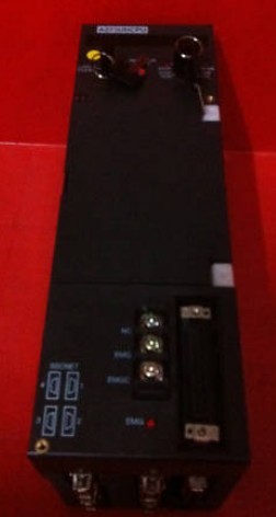
MITSUBISHI A273UHCPU Manual And Instructions
A273UHCPU Common InstructionsProgramming Manual
A273UHCPU Dedicated InstructionsProgramming Manual
A273UHCPU FundamentalsProgramming Manual
A273UHCPU User's Manual
A273UHCPU (SV13/22)(REAL MODE)Programming Manual
A273UHCPU (SV22)(VIRTUAL MODE)Programming Manual
MITSUBISHI A273UHCPU Product information and technical parameters:
Brand: MITSUBISHI
Name: cpu module
Model: A273UHCPU
...More relevant models >>>>
A273UHCPU Common InstructionsProgramming Manual
A273UHCPU Dedicated InstructionsProgramming Manual
A273UHCPU FundamentalsProgramming Manual
A273UHCPU User's Manual
A273UHCPU (SV13/22)(REAL MODE)Programming Manual
A273UHCPU (SV22)(VIRTUAL MODE)Programming Manual
MITSUBISHI A273UHCPU Product information and technical parameters:
Brand: MITSUBISHI
Name: cpu module
Model: A273UHCPU
SI/QSI/H-PCF/ wide range H-PCF fiber optic cable.
Double loop.
Remote I/O network (remote control station).
How to choose MITSUBISHI PLC.
MITSUBISHI PLC options include the choice of MITSUBISHI PLC models, capacity, I/O module, power, etc..
MITSUBISHI PLC distribution I/O points and design MITSUBISHI PLC peripheral hardware circuit
Draw the I/O point of the PLC and the input / output device connection diagram or the corresponding table,
This part also can be carried out in second steps MITSUBISHI A273UHCPU A273UHCPU
Design PLC peripheral hardware circuit.
Draw the electrical wiring diagram of the other parts of the system,
Including the main circuit and the control circuit does not enter the PLC, etc..
The electrical schematic diagram of the system composed of I/O PLC connection diagram and PLC peripheral electrical circuit diagram MITSUBISHI A273UHCPU.
So far the system''s hardware electrical circuit has been determined. GI fiber optic cable.
Double circuit.
MELSECNET (II) (remote I/O station).
According to the control requirements of the system, using the appropriate design method to design MITSUBISHI PLC program.
Procedures to meet the requirements of system control as the main line,
Write one by one to achieve the control function or the sub task of the program,
Gradually improve the functions specified by the system MITSUBISHI A273UHCPU.
MITSUBISHI PLC initialization procedure. After MITSUBISHI PLC on power, the general need to do some of the initial operation,
In order to start making necessary preparations, to avoid the wrong operation of the system.
The main contents of the initialization program are: to some data area, counter and so on,
Data needed to restore some of the data area,
Set or reset some relays,
For some initial state display, etc.. Ethernet network module 10BASE-T/10BASE5
Equipment layer / field bus CC-Link device layer is the PLC and other control devices and sensors and drive devices connected to the field network,
Network for the lowest layer of the whole network system.
Using CC-Link field bus connection, the number of wiring is greatly reduced,
Improve the maintainability of the system.
And, not just the amount of data ON/OFF and other switches,
Can also be connected to the ID system, bar code readder, inverter, man-machine interface and other intelligent devices,
From the completion of a variety of data communication, the management of the terminal production information can be realized,
On the centralized management of the state oof the machine movement,
Make maintenance work efficiency also greatly improved A273UHCPU A273UHCPU.
Q series PLC in the use of CC-Link function better,
And easier to use.
...More relevant models >>>>