 LK Automation Limited
Brand:
MITSUBISHI
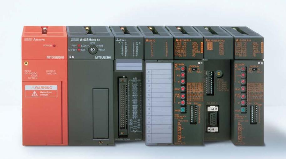
A1SJ71QC24 | MITSUBISHI Serial communication module A1SJ71QC24
MITSUBISHI A1SJ71QC24 Manual And Instructions
A1SJ71QC24 datasheetPDF datasheet
A1SJ71QC24 User's Manual
A1SJ71QC24 Modem Function Additional VersionUser's Manual
MITSUBISHI A1SJ71QC24 Product information and technical parameters:
Brand: MITSUBISHI
Name: Serial communication module
Model: A1SJ71QC24
RS-232 1 channel.
RS-422/485 1 channel.
Transfer speed: 0.3-19.2kbps.
Input status and input information input from the input interface,
CPU will be stored in the working data memory or in the input image register.
And then combine the data and the program with CPU.
The result is stored in the output image register or the working data memory,
And then output to the output interface, control the external drive.
Semiconductor circuit with memory function.
System program memory and user memory.
System program memory for storing system program,
Including management procedures, monitoring procedures, as well as the user program to do the compiler to compile the process of interpretation.
Read only memory. Manufacturers use, content can not be changed, power does not disappear.
...More relevant models >>>>
A1SJ71QC24 datasheetPDF datasheet
A1SJ71QC24 User's Manual
A1SJ71QC24 Modem Function Additional VersionUser's Manual
MITSUBISHI A1SJ71QC24 Product information and technical parameters:
Brand: MITSUBISHI
Name: Serial communication module
Model: A1SJ71QC24
RS-232 1 channel.
RS-422/485 1 channel.
Transfer speed: 0.3-19.2kbps.
Input status and input information input from the input interface,
CPU will be stored in the working data memory or in the input image register.
And then combine the data and the program with CPU.
The result is stored in the output image register or the working data memory,
And then output to the output interface, control the external drive.
Semiconductor circuit with memory function.
System program memory and user memory.
System program memory for storing system program,
Including management procedures, monitoring procedures, as well as the user program to do the compiler to compile the process of interpretation.
Read only memory. Manufacturers use, content can not be changed, power does not disappear.
Program memory capacity: 8k.
Input / output points: maximum 256 points.
A scan cycle of PLC must pass through three stages: input sampling, program execution and output refresh.
PLC in the input sampling phase: first of all, in order to scan the sequence of all existing input latches in the input terminal of the state or input data read,
And write it into the corresponding input status register,
Refresh the input, then close the input port, enter the program execution stage MITSUBISHI A1SJ71QC24 A1SJ71QC24 AnS, QnAS bus connection, the reader to write program 2 channel connection.Data format: RTU.
Data bits: 8.
A1SJ71UC24-R2-S2 and A1SJ71UC24-R4-S2 allow the Ans series PLC to be connected to the MODBUS network,
As the network from the station, and in accordance with the instructions of the main station of the CPU Ans user storage area for data reading / writing MITSUBISHI A1SJ71QC24.
In addition to supporting the MODBUS protocol, these components also support the standard dedicated communication protocol for A1SJ71UC24 components.
This feature makes the main station of the data acquisition and control with more flexibility.
Support MODBUS slave station protocol MITSUBISHI A1SJ71QC24.
Supports 1 to 21 function code.
Two transmission modes: RTU or ASCII. Type of input: DC source.
Input points: 32 points.
Input voltage: DC24.
Input current: 7mA.
Connection mode: terminal row.
Common common point: 32.
Sequential function flow chart language is designed to satisfy the sequential logic control.
The process of sequential process action is divided into steps and transformation conditions,
According to the transfer condition, the control system is distributed in the function flow sequence,
Step by step according to the sequence of actions.
Each step represents a control function, represented by the box.
In the box, the ladder logic is used to complete the task of the corresponding control function.
This programming language makes the program structure clear and easy to read and maintain,
Greatly reduce the programming workload, shorten the programming and debugging time.
Used in the system of the size of the school, procedures for more complex occasions.
Sequence function flow chart programming language features: to function as the main line, in accordance with the functionaal flow of the order of distribution, clear, easy to understand the user program,
Avoid the defect of ladder diagram or other languages,
At the same time, the use of ladder language to avoid the use of ladder programming,
Due to the compllicated mechanical interlock, the structure of the user program is complex and difficult to understand,
User program scan time is also greatly reduced A1SJ71QC24 A1SJ71QC24.
...More relevant models >>>>