 LK Automation Limited
Brand:
MITSUBISHI
A1SJ71ID2-R4 | MITSUBISHI Reader module A1SJ71ID2-R4
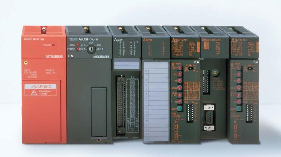
MITSUBISHI A1SJ71ID2-R4 Manual And Instructions
A1SJ71ID2-R4 datasheetPDF datasheet
A1SJ71ID2-R4 User's Manual
MITSUBISHI A1SJ71ID2-R4 Product information and technical parameters:
Brand: MITSUBISHI
Name: Reader module
Model: A1SJ71ID2-R4
AnS, QnAS bus connection, the reader to write program 2 channel connection.
...More relevant models >>>>
A1SJ71ID2-R4 datasheetPDF datasheet
A1SJ71ID2-R4 User's Manual
MITSUBISHI A1SJ71ID2-R4 Product information and technical parameters:
Brand: MITSUBISHI
Name: Reader module
Model: A1SJ71ID2-R4
AnS, QnAS bus connection, the reader to write program 2 channel connection.
Type of input: DC source.
Input points: 16 points.
Input voltage: DC24.
Input current: 7mA.
Connection mode: terminal row.
Common common point: 16.
Functional block diagram language is a kind of PLC programming language, which is similar to digital logic circuit.
The function module is used to represent the function of the module,
Different function modules have different functions MITSUBISHI A1SJ71ID2-R4 A1SJ71ID2-R4
Functional module figure programming language features: functional block diagram programming language is characterized by a functional module for the unit,
Analysis and understanding of the control scheme is simple and easy: function module is to use graphical form of expression,
Intuitive, for a digital logic circuit based on the design of the staff is very easy to master the programming;
Control system with complex scale and complex control logic,
Because the function module diagram can clearly express the function relation, the programming debugging time is greatly reduced MITSUBISHI A1SJ71ID2-R4. SRAM+E2PROM memory card.
RAM capacity: 64KB.
E2PROM capacity: 64KB. RS-232 1 channel.
RS-422/485 1 channel.
Transfer speed: 2 channels MITSUBISHI A1SJ71ID2-R4.
A total of 115.2kbps.
Input status and input information input from the input interface,
CPU will be stored in the working data memory or in the input image register.
And then combine the data and the program with CPU.
The result is stored in the output image register or the working data memory,
And then output to the output interface, control the external drive.
Semiconductor circuit with memory function.
System program memory and user memory.
System program memory for storing system program,
Including management procedures, monitoring procedures, as well as the user program to do the compiler to compile the process of interpretation.
Read only memory. Manufacturers use, content can not be changed, power does not disappear. SRAM memory card.
RAM capacity: 256KB. Output type: transistor drain.
Output points: 16 points.
Load voltage: DC24.
Load current: 2A.
Connection mode: terminal row.
Common public end points: 8.
Switching value, also known as logic, refers to only two values, 0 or 1, ON or OFF.
It is the most common control, it is the advantage of PLC control,
Is also the most basic application of PLC.
Switch volume control is designed to,
According to the current input combbination of the switch quantity and the history of the input sequence,
So that PLC generates the corresponding switching output,
In order to make the system work in a certain order A1SJ71ID2-R4.
So, sometimes also known as the order control.
And seqquential control is divided into manual, semi-automatic or automatic A1SJ71ID2-R4.
And the control principle is decentralized, centralized and hybrid control three.
...More relevant models >>>>