 LK Automation Limited
Brand:
MITSUBISHI
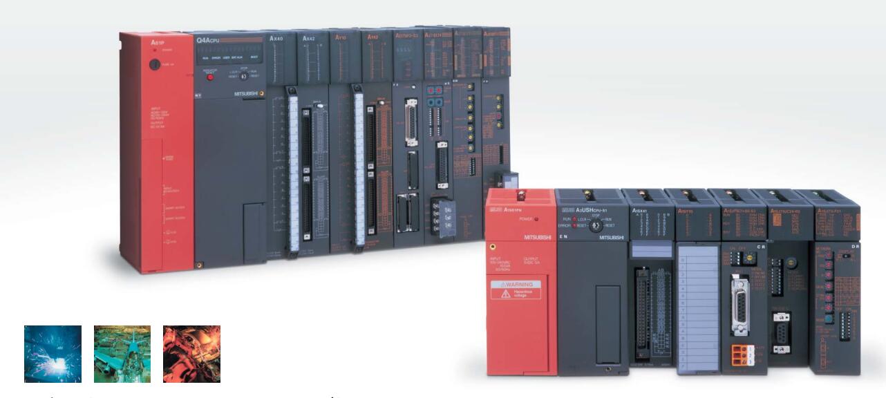
A0J2E-E28DT | MITSUBISHI Extension module A0J2E-E28DT
MITSUBISHI A0J2E-E28DT Manual And Instructions
A0J2E-E28DT datasheetPDF datasheet
A0J2E-E28DT User's Manual
MITSUBISHI A0J2E-E28DT Product information and technical parameters:
Brand: MITSUBISHI
Name: Extension module
Model: A0J2E-E28DT
...More relevant models >>>>
A0J2E-E28DT datasheetPDF datasheet
A0J2E-E28DT User's Manual
MITSUBISHI A0J2E-E28DT Product information and technical parameters:
Brand: MITSUBISHI
Name: Extension module
Model: A0J2E-E28DT
Remote I/O controller, coaxial cable, coaxial loop system.
How to choose MITSUBISHI PLC.
MITSUBISHI PLC options include the choice of MITSUBISHI PLC models, capacity, I/O module, power, etc..
MITSUBISHI PLC distribution I/O points and design MITSUBISHI PLC peripheral hardware circuit
Draw the I/O point of the PLC and the input / output device connection diagram or the corresponding table,
This part also can be carried out in second steps MITSUBISHI A0J2E-E28DT A0J2E-E28DT
Design PLC peripheral hardware circuit.
Draw the electrical wiring diagram of the other parts of the system,
Including the main circuit and the control circuit does not enter the PLC, etc..
The electrical schematic diagram of the system composed of I/O PLC connection diagram and PLC peripheral electrical circuit diagram MITSUBISHI A0J2E-E28DT.
So far the system''s hardware electrical circuit has been determined. Cable 3M for the expansion of the floor, the expansion of a floor for every 1 units.GI fiber optic cable.
Dual loop for Q mode.
Remote I/O network (remote control station).
How to choose MITSUBISHI PLC.
MITSUBISHI PLC options include the choice of MITSUBISHI PLC models, capacity, I/O module, power, etc MITSUBISHI A0J2E-E28DT. .
MITSUBISHI PLC distribution I/O points and design MITSUBISHI PLC peripheral hardware circuit
Draw the I/O point of the PLC and the input / output device connection diagram or the corresponding table,
This part also can be carried out in second steps.
Design PLC peripheral hardware circuit.
Draw the electrical wiring diagram of the other parts of the system,
Including the main circuit and the control circuit does not enter the PLC, etc..
The electrical schematic diagram of the system composed of I/O PLC connection diagram and PLC peripheral electrical circuit diagram.
So far the system''s hardware electrical circuit has been determined. 26 point line conversion adapter 1 line type 16 input CC-Link unit installation special connection conversion adapterInput voltage range: AC100-120V/AC200-240V.
Output voltage: DC5/24V.
Output current: 5/0.8A.
PLC selection with the development of PLC technology, more and more types of PLC products,
Function is becoming moree and more perfect, and its application is more and more extensive A0J2E-E28DT.
Different series of different models of PLC has different performance, applicable occasions also have different emphasis,
Price also has a greater difference. Therefore PLC selection,
Under the premise of meeting the control requirements,
Should consider the best performance to price ratio, a reasonable choice of PLC A0J2E-E28DT.
How to choose MITSUBISHI PLC.
MITSUBISHI PLC options include the choice of MITSUBISHI PLC models, capacity, I/O module, power, etc..
MITSUBISHI PLC distribution I/O points and design MITSUBISHI PLC peripheral hardware circuit
Draw the I/O point of the PLC and the input / output device connection diagram or the corresponding table,
This part also can be carried out in second steps MITSUBISHI A0J2E-E28DT A0J2E-E28DT
Design PLC peripheral hardware circuit.
Draw the electrical wiring diagram of the other parts of the system,
Including the main circuit and the control circuit does not enter the PLC, etc..
The electrical schematic diagram of the system composed of I/O PLC connection diagram and PLC peripheral electrical circuit diagram MITSUBISHI A0J2E-E28DT.
So far the system''s hardware electrical circuit has been determined. Cable 3M for the expansion of the floor, the expansion of a floor for every 1 units.GI fiber optic cable.
Dual loop for Q mode.
Remote I/O network (remote control station).
How to choose MITSUBISHI PLC.
MITSUBISHI PLC options include the choice of MITSUBISHI PLC models, capacity, I/O module, power, etc MITSUBISHI A0J2E-E28DT. .
MITSUBISHI PLC distribution I/O points and design MITSUBISHI PLC peripheral hardware circuit
Draw the I/O point of the PLC and the input / output device connection diagram or the corresponding table,
This part also can be carried out in second steps.
Design PLC peripheral hardware circuit.
Draw the electrical wiring diagram of the other parts of the system,
Including the main circuit and the control circuit does not enter the PLC, etc..
The electrical schematic diagram of the system composed of I/O PLC connection diagram and PLC peripheral electrical circuit diagram.
So far the system''s hardware electrical circuit has been determined. 26 point line conversion adapter 1 line type 16 input CC-Link unit installation special connection conversion adapterInput voltage range: AC100-120V/AC200-240V.
Output voltage: DC5/24V.
Output current: 5/0.8A.
PLC selection with the development of PLC technology, more and more types of PLC products,
Function is becoming moree and more perfect, and its application is more and more extensive A0J2E-E28DT.
Different series of different models of PLC has different performance, applicable occasions also have different emphasis,
Price also has a greater difference. Therefore PLC selection,
Under the premise of meeting the control requirements,
Should consider the best performance to price ratio, a reasonable choice of PLC A0J2E-E28DT.
...More relevant models >>>>