 LK Automation Limited
Brand:
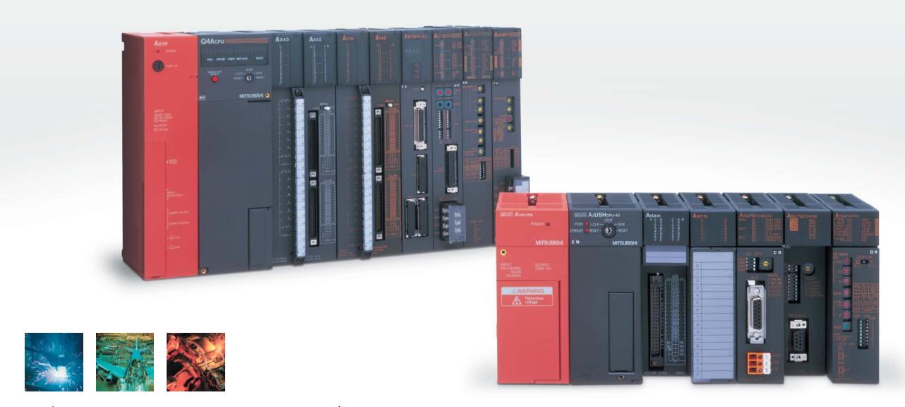
MITSUBISHI
A0J2-E56AR | MITSUBISHI AC input / relay output module A0J2-E56AR
MITSUBISHI A0J2-E56AR Manual And Instructions
A0J2-E56AR datasheetPDF datasheet
A0J2-E56AR User's Manual
MITSUBISHI A0J2-E56AR Product information and technical parameters:
Brand: MITSUBISHI
Name: AC input / relay output module
Model: A0J2-E56AR
Input points: 32 points.
Input voltage and current: 120V ~ 10mA AC100.
Input response time: 35ms.
16 point /1 a public side.
Output points: 24 points.
Output voltage: DC24V/AC240V, 2A/1 point, 5A/1 common end.
Output response time: 12ms.
Output type: relay output.
8 point /1 a public side.
36 point terminal station.
Control solenoid valve required I/O points by the action principle of the solenoid valve can be known,
A single coil solenoid valve with PLC control to 2 input and 1 output,
A double coil solenoid valve requires 3 inputs and 2 outputs,
A button needs an input; a light sensitive switch needs 4 or 2 inputs,
A signal lamp needs 1 output, band switch,
Several bands are required for several inputs,
In general, a variety of position switches are required to take up 2 input points.
MITSUBISHI PLC is the main product in the production of MITSUBISHI motor in Dalian.
It uses a kind of programmable memory for its internal storage procedures,
Execute logic operation, sequence control, timing, counting and arithmetic operations, user oriented instruction,
And through digital or analog input / output control of various types of machinery or production process.
The number of I/O thyristor DC motor control required tube DC motor speed control system is the main form of DC speed regulation,
The thyristor rectifier unit is used to supply power to the DC motor.
PLC control of the DC drive system, the input of the PLC in addition to the main signal outside the signal,
We need to consider the switching signal, the fault signal transmission device, brake signal and fan fault signal.
The output of the PLC mainly consider the speed command signal positive 1~3 level, 1~3 level, allowing reverse switching signal and brake open signal etc..
In general, a reversible DC drive system controlled by PLC is approximately 12 input points and 8 output points,
An irreversible DC drive system requires 9 inputs and 6 output points.
...More relevant models >>>>
A0J2-E56AR datasheetPDF datasheet
A0J2-E56AR User's Manual
MITSUBISHI A0J2-E56AR Product information and technical parameters:
Brand: MITSUBISHI
Name: AC input / relay output module
Model: A0J2-E56AR
Input points: 32 points.
Input voltage and current: 120V ~ 10mA AC100.
Input response time: 35ms.
16 point /1 a public side.
Output points: 24 points.
Output voltage: DC24V/AC240V, 2A/1 point, 5A/1 common end.
Output response time: 12ms.
Output type: relay output.
8 point /1 a public side.
36 point terminal station.
Control solenoid valve required I/O points by the action principle of the solenoid valve can be known,
A single coil solenoid valve with PLC control to 2 input and 1 output,
A double coil solenoid valve requires 3 inputs and 2 outputs,
A button needs an input; a light sensitive switch needs 4 or 2 inputs,
A signal lamp needs 1 output, band switch,
Several bands are required for several inputs,
In general, a variety of position switches are required to take up 2 input points.
MITSUBISHI PLC is the main product in the production of MITSUBISHI motor in Dalian.
It uses a kind of programmable memory for its internal storage procedures,
Execute logic operation, sequence control, timing, counting and arithmetic operations, user oriented instruction,
And through digital or analog input / output control of various types of machinery or production process.
The number of I/O thyristor DC motor control required tube DC motor speed control system is the main form of DC speed regulation,
The thyristor rectifier unit is used to supply power to the DC motor.
PLC control of the DC drive system, the input of the PLC in addition to the main signal outside the signal,
We need to consider the switching signal, the fault signal transmission device, brake signal and fan fault signal.
The output of the PLC mainly consider the speed command signal positive 1~3 level, 1~3 level, allowing reverse switching signal and brake open signal etc..
In general, a reversible DC drive system controlled by PLC is approximately 12 input points and 8 output points,
An irreversible DC drive system requires 9 inputs and 6 output points.
A6WU-A6PHP/A6HGP connection cable.
Length: 0.3m. Position detection axis number: 1 axis.
Resolution: 4096.
Number of output channels: 16 channels.
When communicating in the PLC network of MITSUBISHI,
There is no sense of difference and discontinuity in the network,
Can carry on the remote monitoring, modification, debugging and other work of data communication and program,
Without taking into account the level and type of network MITSUBISHI A0J2-E56AR A0J2-E56AR
MELSECNET/H and CC-Link use the way of loop communication,
Periodically automatically send and receive messages,
Does not require specialized data communication procedures,
Simple parameters can be set.
MELSECNET/H and CC-Link are used to transmit and receive the broadcast mode,
This can be done on the network data sharing MITSUBISHI A0J2-E56AR.
For the use of Ethernet, MELSECNET/H, CC-Link network,
Can set the network parameters and various functions, simple and convenient in the Developer GX software screen. 10BASE5/10BASE2
When communicating in the PLC network of MITSUBISHI,
There is no sense of difference and discontinuity in the network,
Can carry on the remote monitoring, modification, debugging and other work of data communication and program,
Without taking into account the level and type of network MITSUBISHI A0J2-E56AR.
MELSECNET/H and CC-Link use the way of loop communication,
Periodically automatically send and receive messages,
Does not require specialized data communication procedures,
Simple parameters can be set.
MELSECNET/H and CC-Link are used to transmit and receive the broadcast mode,
This can be done on the network data sharing.
For the use of Ethernet, MELSECNET/H, CC-Link network,
Can set the network parameters and various functions, simple and convenient in the Developer GX software screen. Multi axis positioning controller.
Optical data communication line.
Program capacity: Max 60K step.
Input / output points: 1920 points.
The length of time required to execute the instruction, the length of the user''s program, the type of instruction, and the speed of the CPU execution are very significant,
Generally, a scanning process, the fault diagnosis time,
Communication time, input sampling and output refresh time is less,
The execution time is accounted for the vast majority of.
The photoelectric coupler is composed of two luminous two extreme tubes and a photoelectric transistor.
Light emitting diode two: the input of a photo coupler and the change of electrical signal,
The light signal is generated by the light emitting diode, which is the same as the input signal.
The working process of the input interface circuit: when the switch is closed, the diode light,
The transistor is then guided to the internal circuit and input signal under the irradiation of the light.
When the switch is off, the diode does not emit light, and the transistor is not on the way. Internal circuit input signal.
It is through the input interface circuit to the external switch signal into PLC internal can accept the digital signal.
Photoelectric three levels: in the light of the light signal conduction, the degree of light signal and the intensity of the light signal.
The output signal has a linear relationship with the input signal in the linear operating region of the photoelectric coupler.
User program storage capacity: it is a measure of how much the user application can store the number of indicators A0J2-E56AR.
Usually in words or K words as units. 16 bit binary number is a word,
Every 1024 words are 1K words. PLC to store instructions and data in words.
General llogical operation instructions each account for 1 words A0J2-E56AR. Timer / counter,
Shift instruction accounted for 2 words. Data operation instructions for 2~4.
...More relevant models >>>>