Brand Sort:
MITSUBISHI
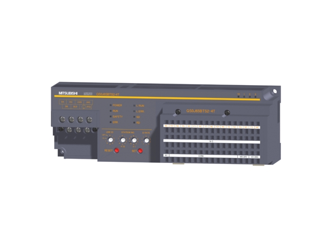
QS0J65BTS2-4T Market price | QS0J65BTS2-4T Introduction
- Brand: MITSUBISHI
- Country: JAPAN
- Name: Safety CC-Link system remote I/O module
- Model: QS0J65BTS2-4T
- Price: 0 >
MITSUBISHI QS0J65BTS2-4T
Use: this option can be selected from the open collector output can output 2 analog signal from the transducer output signal in the standard 6 digital signal.
Applicable frequency converter: FR-A700, FR-F700, FR-E700. "Length: 3m.
Specification: D-sub 25 pin (male), D-sub 25 pin (male). Pulse input: differential input.
Preset input: differential input.
Count range: 0~16777215.
Number of stations: 4 stops QS0J65BTS2-4T
Station type: remote equipment station.
Configuration of master / local station,
In addition to the other site network with different CC-Link in addition to the main station and the remote station configuration can also be the main station and the local station configuration.
A local PLC can communicate with the master station PLC and other remote workstations.
MITSUBISHI PLC hardware implementation
Hardware implementation is mainly for the control cabinet and other hardware design and field construction.
Design control cabinet and the operating table and other parts of the electrical wiring diagram and wiring diagram.
Electrical interconnection diagram of each part of the design system.
According to the construction drawings of the site wiring, and carry out a detailed inspection.
Because the program design and hardware implementation can be carried out at the same time,
So the design cycle of the MITSUBISHI PLC control system can be greatly reduced.
MITSUBISHI PLC online debugging.
On-line debugging is the process that will through the simulation debugging to further carry on the on-line unification to adjust.
On-line debugging process should be step by step,
From MITSUBISHI PLC only connected to the input device, and then connect the output device, and then connect to the actual load and so on and so on step by step.
If you do not meet the requirements, the hardware and procedures for adjustment.
Usually only need to modify the part of the program can be. Motor series: ultra low inertia, small capacity.
Using a serial absolute / incremental encoder.
Rated output power: 0.05kw.
Rated speed: 3000rpm.
With the brake with brake.
Without GB.
Shaft end: straight shaft.
The rotor of the servo motor is a permanent magnet, and the control of the servo amplifier is controlled by the U/V/W three-phase electric electromagnetic field,
The rotor rotates under the action of the magnetic field, and the encoder feedback signal of the motor is given to the driver,
According to the feedback value and the target value, the driver is compared,
Adjust the rotor rotation angle.
The accuracy of the servo motor is determined by the resolution of the encoder.
QS0J65BTS2-4T Operation manual/Instructions/Model selection sample download link: /searchDownload.html?Search=QS0J65BTS2-4T&select=5
...more relevant model market price >>>>
Related products
MITSUBISHI
Safety CC-Link system remote I/O module
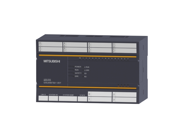
QS0J65BTB2-12DT

Input points: 8 points dual input, 16
MITSUBISHI
Safety CC-Link system remote I/O module
QS0J65BTS2-4T

Output points: 4 points select the sour
MITSUBISHI
Safety CC-Link system remote I/O module
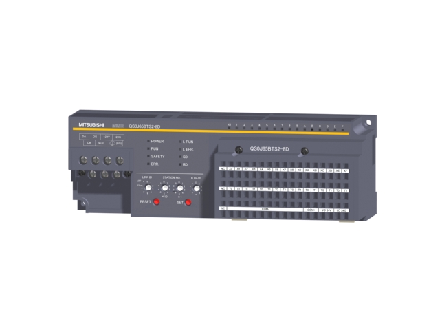
QS0J65BTS2-8D

Input points: 8 points dual input, 16
