Brand Sort:
MITSUBISHI
QJ71C24N-R4 Market price | QJ71C24N-R4 Introduction
- Brand: MITSUBISHI
- Country: JAPAN
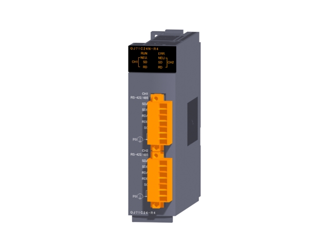
- Name: Serial communication module (upgrade)
- Model: QJ71C24N-R4
- Price: U.S.$ 1005.08
MITSUBISHI QJ71C24N-R4
MITSUBISHI inverter FR-F740 series.
Voltage level: three phase 400V.
Frequency converter capacity: 500KW.
The main circuit of the inverter can be divided into two categories in general: voltage type is the voltage source of the DC converter for AC inverter,
The filtering of the DC circuit is the capacitance; the current mode is the DC conversion of the current source to the AC inverter,
The DC loop filter is the inductor QJ71C24N-R4
Why is the frequency of the inverter voltage proportional to the change?
The electromagnetic torque of any motor is the result of the interaction between the current and the magnetic flux, the current is not allowed to exceed the rated value, otherwise it will cause the heating of the motor.
Therefore, if the magnetic flux decreases, the electromagnetic torque will decrease, which leads to the reduction of the load carrying capacity. The length of the line: 5M.
IP level: IP65.
Cable lead out direction: motor shaft different side.
Bending life: high bending life.
The cable is not shielded.
Encoder with cable (motor side); for HF-KP/HF-MP series (motor shaft with side extraction). The length of the line: 20M.
Relay type.
IP level: IP20.
Bending life: high bending life.
Encoder with cable (amplifier side); for HF-KP/HF-MP series. Length: 3 meters.
Connection between a connector adapter box and a smart GOT.
Applicable model: HandyGOT. Pulse input: differential input.
Preset input: differential input.
Count range: 0~16777215.
Number of stations: 4 stops.
Station type: remote equipment station.
Configuration of master / local station,
In addition to the other site network with different CC-Link in addition to the main station and the remote station configuration can also be the main station and the local station configuration.
A local PLC can communicate with the master station PLC and other remote workstations.
MITSUBISHI PLC hardware implementation
Hardware implementation is mainly for the control cabinet and other hardware design and field construction.
Design control cabinet and the operating table and other parts of the electrical wiring diagram and wiring diagram.
Electrical interconnection diagram of each part of the design system.
According to the construction drawings of the site wiring, and carry out a detailed inspection.
Because the program design and hardware implementation can be carried out at the same time,
So the design cycle of the MITSUBISHI PLC control system can be greatly reduced.
MITSUBISHI PLC online debugging.
On-line debugging is the process that will through the simulation debugging to further carry on the on-line unification to adjust.
On-line debugging process should be step by step,
From MITSUBISHI PLC only connected to the input device, and then connect the output device, and then connect to the actual load and so on and so on step by step.
If you do not meet the requirements, the hardware and procedures for adjustment.
Usually only need to modify the part of the program can be.
QJ71C24N-R4 Operation manual/Instructions/Model selection sample download link: /searchDownload.html?Search=QJ71C24N-R4&select=5
...more relevant model market price >>>>
Related products
MITSUBISHI
Serial communication module (upgrade)
QJ71C24N-R4

RS-422/485.
2 channel.
Transmission spee
MITSUBISHI
Serial communication module
QJ71C24-R2

"2CH RS-232.
QJ71C24N -R2 through the
MITSUBISHI
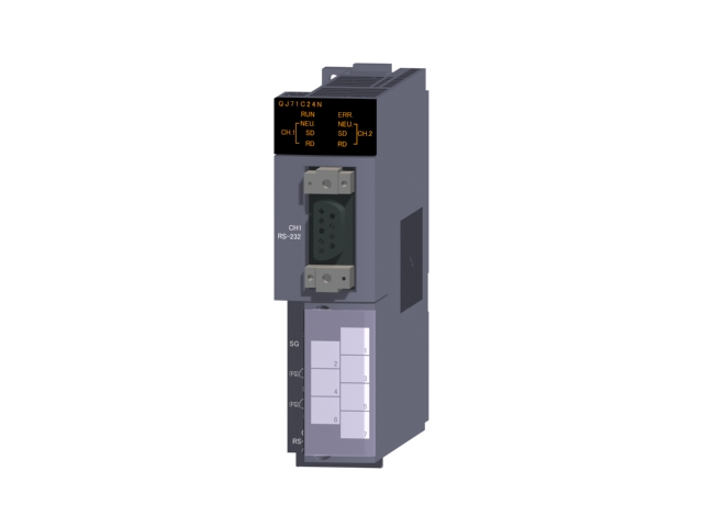
Serial communication module (upgrade)
QJ71C24N

RS-232 1 channel.
RS-422/485 1 channel.
MITSUBISHI
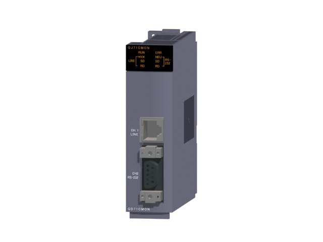
Modem interface module
QJ71CMON

"10BASE-T/100BASE-TX.
"A channel modular
