Brand Sort:
MITSUBISHI
HC-SFS52G1 1/6 Market price | HC-SFS52G1 1/6 Introduction

- Brand: MITSUBISHI
- Country: JAPAN
- Name:
- Model: HC-SFS52G1 1/6
- Price: U.S.$ 2801.69
MITSUBISHI HC-SFS52G1 1/6
RS-232:1, RS-422/485:1.
Transmission speed: 0.3 ~ 19.2kpbs.
Computer connection function.
Printer / peripheral device connection, BASIC language function.
The electrical schematic diagram of the system composed of I/O PLC connection diagram and PLC peripheral electrical circuit diagram.
So far the system''s hardware electrical circuit has been determined.
How to choose MITSUBISHI PLC.
MITSUBISHI PLC options include the choice of MITSUBISHI PLC models, capacity, I/O module, power, etc HC-SFS52G1 1/6.
MITSUBISHI PLC distribution I/O points and design MITSUBISHI PLC peripheral hardware circuit
Draw the I/O point of the PLC and the input / output device connection diagram or the corresponding table,
This part also can be carried out in second steps.
Design PLC peripheral hardware circuit.
Draw the electrical wiring diagram of the other parts of the system,
Including the main circuit and the control circuit does not enter the PLC, etc.. Power: 0.75kw.
Purpose: high frequency braking resistor.
The use rate of the built-in regenerative brake of the transducer can be promoted.
When using the FR-ABR type brake resistor, the short circuit piece between the terminal PR-PX is removed. Does not remove the short circuit chip will lead to overheating of the brake resistor.
The utilization rate of the regenerative braking should be less than the allowable brake use rate in the above table.
With the operating frequency of the brake resistor to reach 300 degrees C or higher, it is necessary to take protective measures and cooling.
MYS type resistor can be used. But please pay attention to the allowable brake use rate.
Do not remove the terminal P/+ and P1 between the short circuit chip, in addition to connecting the DC reactor.
The installation of thermal relay, to avoid overheating and burn the braking resistor. MITSUBISHI motor universal AC servo amplifier MELSERVO-J3 series.
Rated output: 7.0kw.
Interface type: SSCNET type III fiber communication.
Full closed loop control.
Power specification: three phase AC200V.
High precision and high response location control.
Full closed loop control can be realized by double feedback control method.
Dual feedback control can be performed between the servo motor encoder and the load side encoder.
MR-J3-B-RJ006 can be used in conjunction with a number of manufacturers of linear encoder,
Users can build the system according to their own accuracy requirements. ABS type linear encoder using serial interface,
No need to install the battery on the servo amplifier can easily build the absolute position detection system.
Flexible system configuration.
Can achieve higher load side positioning accuracy!
HC-SFS52G1 1/6 Operation manual/Instructions/Model selection sample download link: /searchDownload.html?Search=HC-SFS52G1 1/6&select=5
...more relevant model market price >>>>
Related products
MITSUBISHI
Medium inertia power motor
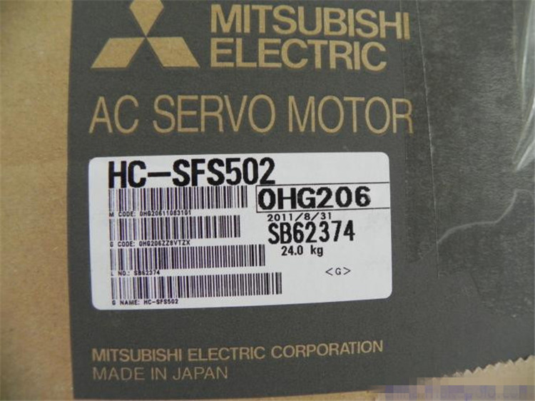
HC-SFS502

Motor series: medium inertia, medium pow
MITSUBISHI
Medium inertia power motor
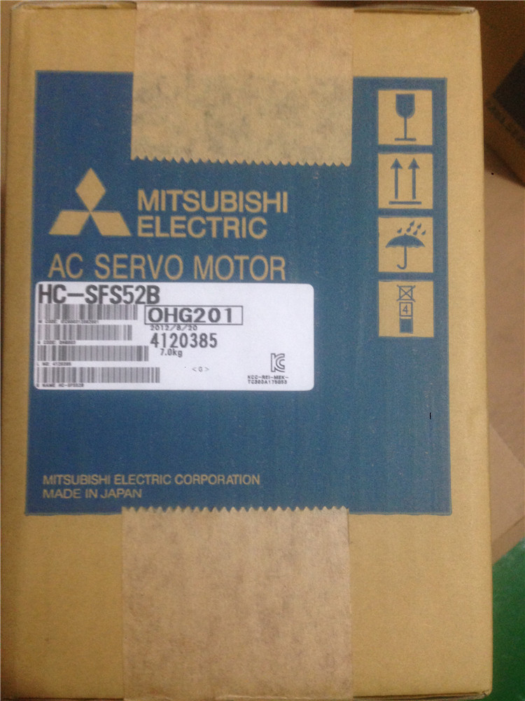
HC-SFS52B

Motor series: medium inertia, medium pow
MITSUBISHI
Medium inertia power motor
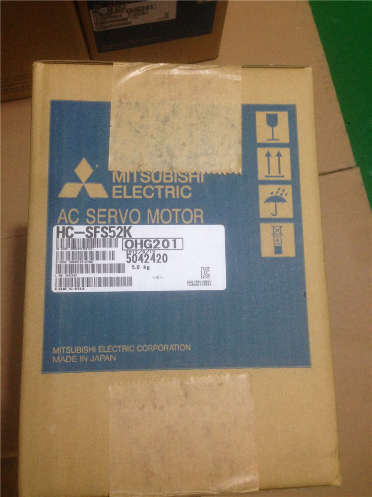
HC-SFS52K

Motor series: medium inertia, medium pow
MITSUBISHI
Medium inertia power motor
HC-SFS53B

Motor series: medium inertia, medium pow
