Brand Sort:
MITSUBISHI
HC-SFS202BG1 1/29 Market price | HC-SFS202BG1 1/29 Introduction

- Brand: MITSUBISHI
- Country: JAPAN
- Name:
- Model: HC-SFS202BG1 1/29
- Price: U.S.$ 6074.58
MITSUBISHI HC-SFS202BG1 1/29
2 axes, open collector output type.
2 axis linear interpolation.
2 axis interpolation.
Control unit: mm, inch, degree, pulse.
Location data: 600 data / axis.
Maximum pulse output: 200Kpps.
40 pin connector.
Positioning module.
Open collector output.
Differential driver output.
Based on the use of open collector outputs and differential drive output type 2 types.
Differential driver output type positioning module can transmit high speed instruction pulse (up to 4Mpps) to the servo amplifier reliably,
Transmission distance of up to 10 meters, to achieve high speed and high precision control HC-SFS202BG1 1/29
(the command pulse of the open collector positioning module is highest 200kpps.)
A variety of modules with excellent performance,
Meet the needs of various control from analog to location.
Q series module products include a variety of types of I/O, analog and positioning function module.
Can fully meet the switch, sensor, such as the input and output, temperature, weight, flow and motor, drive control,
As well as the requirements of high-precision control of the positioning of the industry, the control needs of various fields.
Can also be used in combination with the CPU module to achieve appropriate control.
The possibility of expanding control with intelligent function.
Providing a variety of analog modules, is the ideal choice for process control applications.
Can also meet the needs of high speed, high precision control.
Most suitable analog modules for high speed conversion control.
Can provide a variety of analog and digital analog conversion module products.
These modules have a variety of functions, in the connection of equipment, to achieve the greatest flexibility.
Can meet the inverter control, such as high-speed conversion needs. DC input points: 8 points.
Input voltage and current: 7mA, DC24V.
Response time: 10ms.
8 point /1 a public side.
Positive / negative sharing.
Output points: 8 points.
Output voltage and current: DC24V/AC240V, 2A/1 point, 5A/1 common end.
Response time: 12ms.
8 point /1 a public side.
Output form: relay output.
34 point terminal station.
Number of stations: 2 stops.
According to the control requirements of the system, using the appropriate design method to design MITSUBISHI PLC program.
Procedures to meet the requirements of system control as the main line,
Write one by one to achieve the control function or the sub task of the program,
Gradually improve the functions specified by the system.
MITSUBISHI PLC detection, fault diagnosis and display and other procedures.
These procedures are relatively independent, generally in the basic completion of the program design and then add.
Hardware simulation method is to use a number of hardware equipment to simulate the generation of the signal,
The signals are connected to the input end of the PLC system in a hard wired way, and the timeliness is strong.
Software simulation method is in the MITSUBISHI PLC in the preparation of a set of simulation program,
The simulation provides the field signal, which is simple and easy to operate, but it is not easy to guarantee the timeliness.
Simulation of the process of debugging, debugging method can be used to segment, and the monitoring function of programmer.
HC-SFS202BG1 1/29 Operation manual/Instructions/Model selection sample download link: /searchDownload.html?Search=HC-SFS202BG1 1/29&select=5
...more relevant model market price >>>>
Related products
MITSUBISHI
Medium inertia power motor
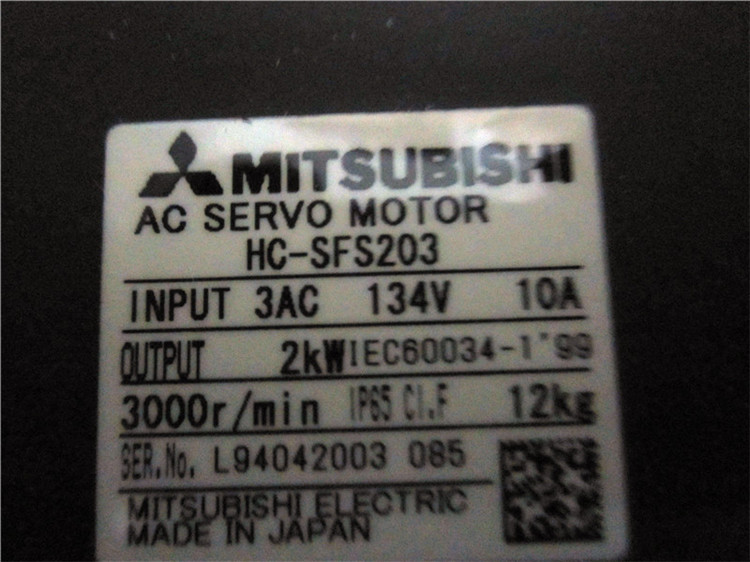
HC-SFS203

Motor series: medium inertia, medium pow
MITSUBISHI
Medium inertia power motor
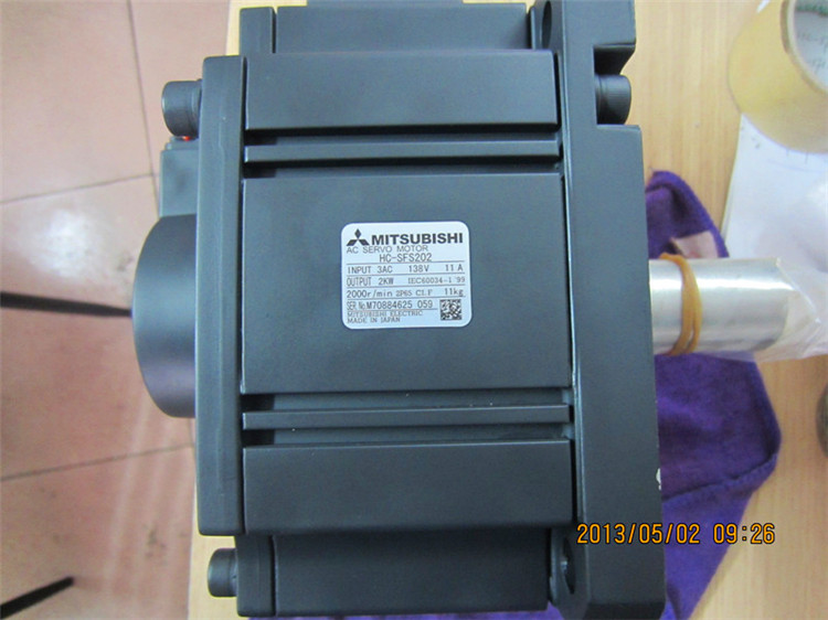
HC-SFS202

Motor series: medium inertia, medium pow
MITSUBISHI
Medium inertia power motor
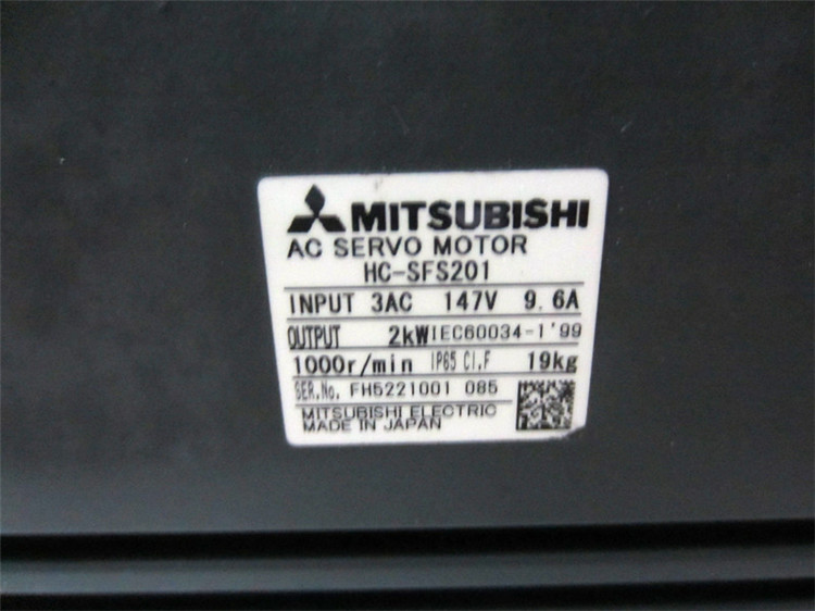
HC-SFS201

Motor series: medium inertia, medium pow
MITSUBISHI
Medium inertia power motor
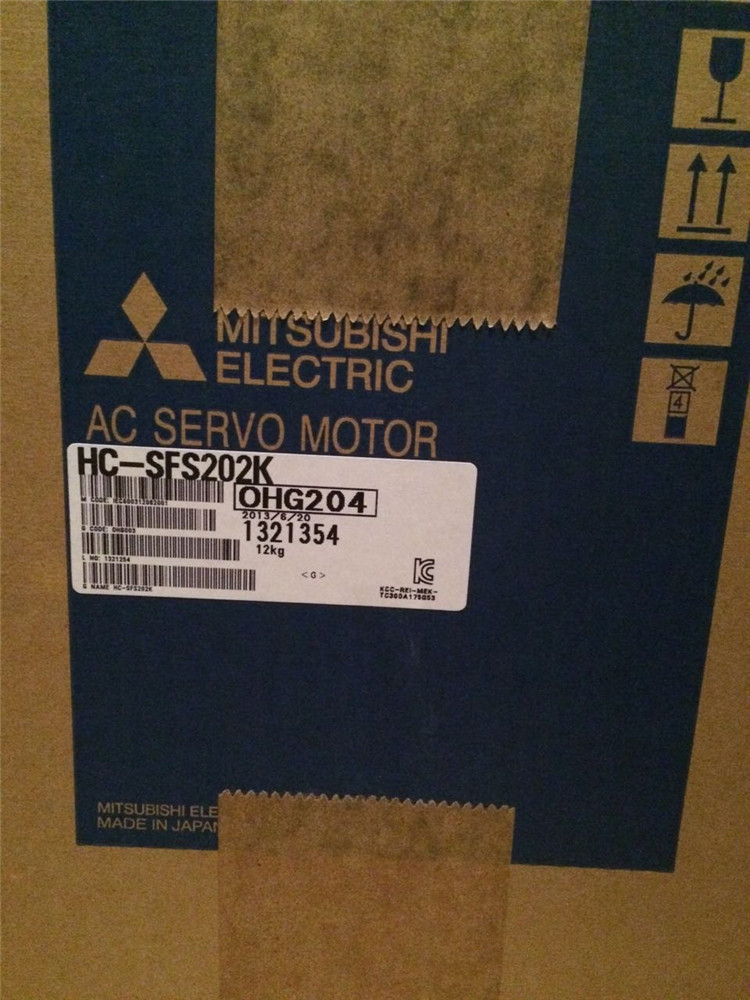
HC-SFS202K

Motor series: medium inertia, medium pow
