Brand Sort:
MITSUBISHI
FX0N-8EYR-ES/UL Market price | FX0N-8EYR-ES/UL Introduction

- Brand: MITSUBISHI
- Country: JAPAN
- Name:
- Model: FX0N-8EYR-ES/UL
- Price: U.S.$ 152.54
MITSUBISHI FX0N-8EYR-ES/UL
Superior high efficiency IPM motor.
Output power: 7.5kw.
Rated speed: 1500r/min.
Voltage level: 200V.
IPM motor MM-EFS series can not be used to run the power frequency power.
The total wiring length of the IPM motor shall not exceed 100m.
1 inverters can not connect multiple IPM motors at the same time. Function: the core function of the condensed display.
Picture size: 3.8 inches.
Resolution: 320 * 128 dot FX0N-8EYR-ES/UL
Display: TFT monochrome.
Panel color: black.
Power type: DC24V.
Communication interface: RS-232 * 2.
Small body equipped with ethernet!
Compared with the past, the upgrade of 320 x 128dot 4 x high resolution lcd.
HD LCD screen.
Equipped with TFT monochrome 32 gray level of high resolution liquid crystal, compact body design and display the effect is clear.
1, SD memory card module with the interface.
Can be installed to buy the SD memory card module, save the alarm and log data.
2, USB interface: device USB (Mini-B USB)
Can connect to the computer to transfer data.
3, RS-422/485 interface.
Can be connected to a variety of FA machines, bar code reader.
4, Ethernet interface.
Up to 2 different manufacturers can be connected to the FA machine.
Backlight color variety, equipment status at a glance.
The use of direct 5 color backlight, according to the production of equipment, respectively, the use of backlight color / flicker.
In addition, the control of the backlight can be carried out by connecting the programmable controller. (picture color switching, ON/OFF/ flashing backlight). SI/QSI/H-PCF/ wide range H-PCF fiber optic cable.
Double loop.
PC inter network (management station / station) / remote I/O network (remote control station).
External power supply function.
How to choose MITSUBISHI PLC.
MITSUBISHI PLC options include the choice of MITSUBISHI PLC models, capacity, I/O module, power, etc..
MITSUBISHI PLC distribution I/O points and design MITSUBISHI PLC peripheral hardware circuit
Draw the I/O point of the PLC and the input / output device connection diagram or the corresponding table,
This part also can be carried out in second steps.
Design PLC peripheral hardware circuit.
Draw the electrical wiring diagram of the other parts of the system,
Including the main circuit and the control circuit does not enter the PLC, etc..
The electrical schematic diagram of the system composed of I/O PLC connection diagram and PLC peripheral electrical circuit diagram.
So far the system''s hardware electrical circuit has been determined.
FX0N-8EYR-ES/UL Operation manual/Instructions/Model selection sample download link: /searchDownload.html?Search=FX0N-8EYR-ES/UL&select=5
...more relevant model market price >>>>
Related products
MITSUBISHI
PLC
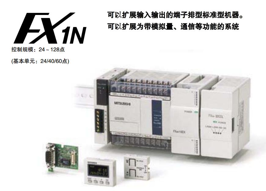
FX1N-40MR-ES/UL

Max input / output points: 40 points.
Su
MITSUBISHI
Input / output module
FX2N-8ER-ES/UL

Input and output form: DC input, relay o
MITSUBISHI
PLC
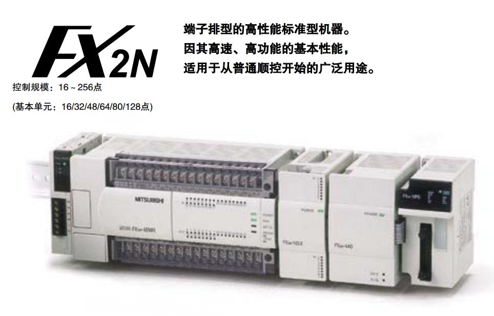
FX2N-16MR-ES/UL

Max input / output points: 16 points.
Su
MITSUBISHI
PLC
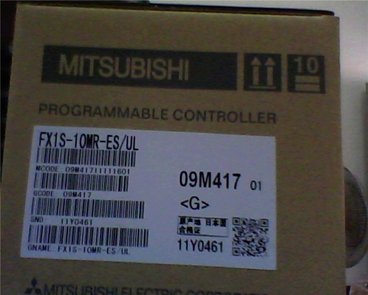
FX1S-10MR-ES/UL

Max input / output points: 10 points.
Su
