Brand Sort:
MITSUBISHI
FX-30P Market price | FX-30P Introduction
- Brand: MITSUBISHI
- Country: JAPAN
- Name: Hand held programmable controller
- Model: FX-30P
- Price: 0 >
MITSUBISHI FX-30P
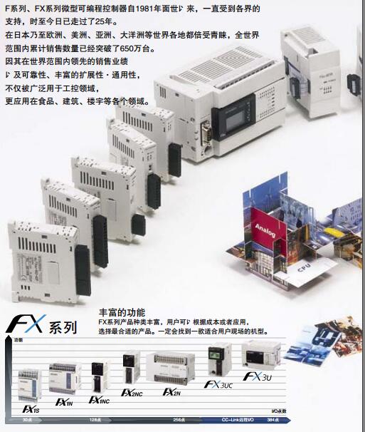
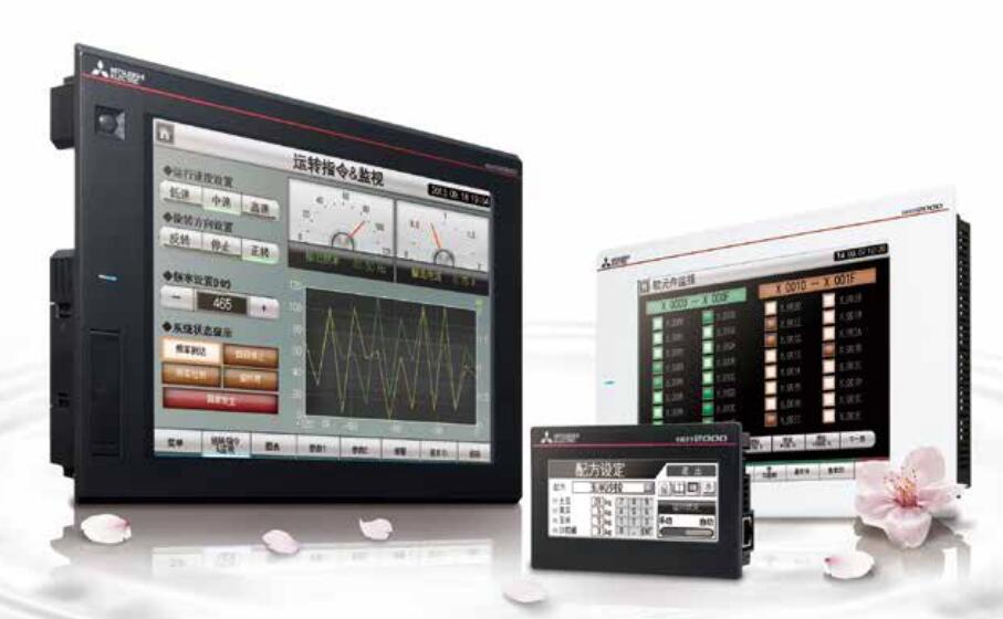
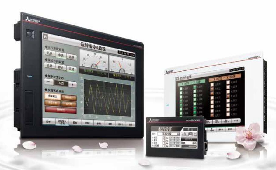
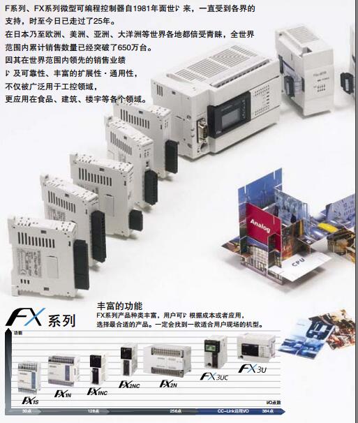
A series of high performance models that are widely used in network or single machine work environments.
Screen size: 12.1 inches.
Display color: 256 color or more color.
Mounting type: panel mounting type.
Resolution: SVGA (800 x 600).
Display device: TFT color (high brightness, wide viewing angle).
Host frame color: black.
Power type: AC100~240V.
Communication interface: with built-in RS-422.
Ideal model for high performance in a network or independent operation environment FX-30P
User storage capacity: 9MB (GT15__-VNB_:5MB).
Device USB port.
Standard RS-232 interface.
Support video /RGB unit.
If the capacitive touch screen is in the middle of the operation, the display resolution or display mode of the touch screen is changed again,
Or the refresh rate of the touch screen controller is adjusted by itself, and the cursor and the touch point can not be felt when the cursor is not corresponding to the touch point,
Must be re calibrated to the touch screen system.
In order to ensure the normal operation of the touch screen system, in addition to ensure the proper installation of the system software,
Must also remember that in a host do not install two or more than two kinds of touch screen driver,
This will cause the system to run in conflict, so that the touch screen system can not be used properly. 3C-2V/5C-2V coaxial cable.
Single bus.
PC inter network (management station / common station) / remote I/O network (remote control station).
How to choose MITSUBISHI PLC.
MITSUBISHI PLC options include the choice of MITSUBISHI PLC models, capacity, I/O module, power, etc..
MITSUBISHI PLC distribution I/O points and design MITSUBISHI PLC peripheral hardware circuit
Draw the I/O point of the PLC and the input / output device connection diagram or the corresponding table,
This part also can be carried out in second steps.
Design PLC peripheral hardware circuit.
Draw the electrical wiring diagram of the other parts of the system,
Including the main circuit and the control circuit does not enter the PLC, etc..
The electrical schematic diagram of the system composed of I/O PLC connection diagram and PLC peripheral electrical circuit diagram.
So far the system''s hardware electrical circuit has been determined.
FX-30P Operation manual/Instructions/Model selection sample download link: /searchDownload.html?Search=FX-30P&select=5
...more relevant model market price >>>>
Related products
MITSUBISHI
Output expansion module
FX-16EYR-ES-TB/UL

Output: 16 points.
Function: relay outpu
MITSUBISHI
Oil resistant cap
GT10-30PCO

Oil resistant cap for 4.5 inch screen.
A
MITSUBISHI
Resist film
GT10-30PSGW

Protective film for 4.5 inch screen.
Scr
MITSUBISHI
Connecting cable
FX-32E-150CAB

Length: 1.5m.
Specification: TB-FX round

