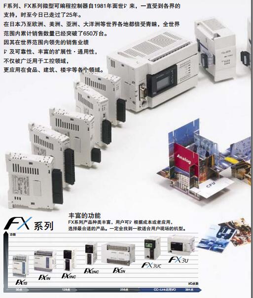
Brand Sort:
MITSUBISHI
FX-232CAB-1 Market price | FX-232CAB-1 Introduction
- Brand: MITSUBISHI
- Country: JAPAN
- Name: Connecting cable
- Model: FX-232CAB-1
- Price: 0 >
MITSUBISHI FX-232CAB-1
MITSUBISHI motor universal AC servo amplifier MELSERVO-J3 series.
Rated output: 5.0kw.
Interface type: SSCNET type III fiber communication.
Special specification: suitable for linear servo motor.
Power specification: three phase AC200V.
More advanced real-time automatic tuning by setting response values,
Including the position gain and the gain of speed, all the gain can be adjusted automatically.
32 segment response level can be set FX-232CAB-1
Advanced vibration suppression control.
An optimal vibration control filter value is automatically set by the automatic tuning function to effectively suppress the vibration of the 100Hz frequency that occurs when the driving part stops.
The automatic tuning function can effectively restrain the vibration of the end of the mechanical arm and reduce the residual vibration in the machine. MITSUBISHI inverter FR-F740 series.
Voltage level: three phase 400V.
Frequency converter capacity: 132KW.
Frequency converter common frequency of a given way: the operator keyboard is given, the contact signal given, analog signal given, the pulse signal given and communication methods given, etc..
These frequencies have their advantages and disadvantages, and should be selected according to the actual needs.
Frequency converter is a power control device which uses the power of the power semiconductor device to change the power frequency to another frequency,
Can realize the asynchronous motor soft start, variable frequency speed regulation, improve the operation precision, change the power factor, over current / over voltage / overload protection and other functions. RS232 cable for connecting cables and 3M, CPU.GI fiber optic cable.
Dual loop for Q mode.
PC inter network (management station / station) / remote I/O network (remote control station).
How to choose MITSUBISHI PLC.
MITSUBISHI PLC options include the choice of MITSUBISHI PLC models, capacity, I/O module, power, etc..
MITSUBISHI PLC distribution I/O points and design MITSUBISHI PLC peripheral hardware circuit
Draw the I/O point of the PLC and the input / output device connection diagram or the corresponding table,
This part also can be carried out in second steps.
Design PLC peripheral hardware circuit.
Draw the electrical wiring diagram of the other parts of the system,
Including the main circuit and the control circuit does not enter the PLC, etc..
The electrical schematic diagram of the system composed of I/O PLC connection diagram and PLC peripheral electrical circuit diagram.
So far the system''s hardware electrical circuit has been determined.
FX-232CAB-1 Operation manual/Instructions/Model selection sample download link: /searchDownload.html?Search=FX-232CAB-1&select=5
...more relevant model market price >>>>
Related products
MITSUBISHI
Connecting cable
FX-232CAB-2
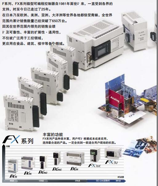
PC-9800 computer half pitch 14 pin
MITSUBISHI
RS-232C/RS-422 converter
FX-232AWC-H
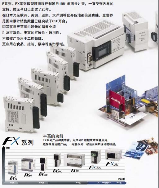
RS-232C/RS-422 converter
MITSUBISHI
RS-422 cable
FX9GT-CAB-10M
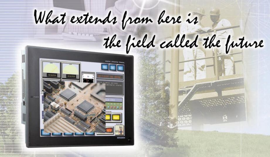
Cale length: 10 meters.
For FXCPU FX0,
MITSUBISHI
Cable for connecting hand held GOT and PLC
F9GT-HCAB-10M
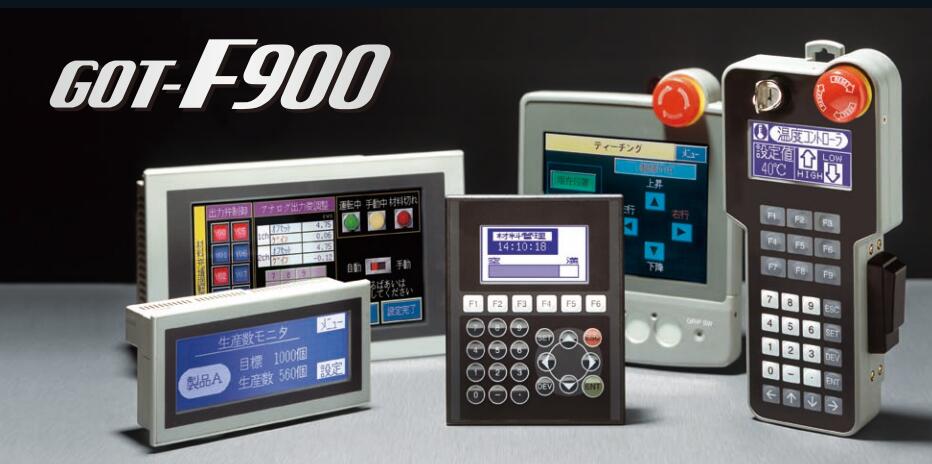
Connecting cale for handheld GOT and PL

