Brand Sort:
MITSUBISHI
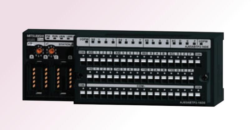
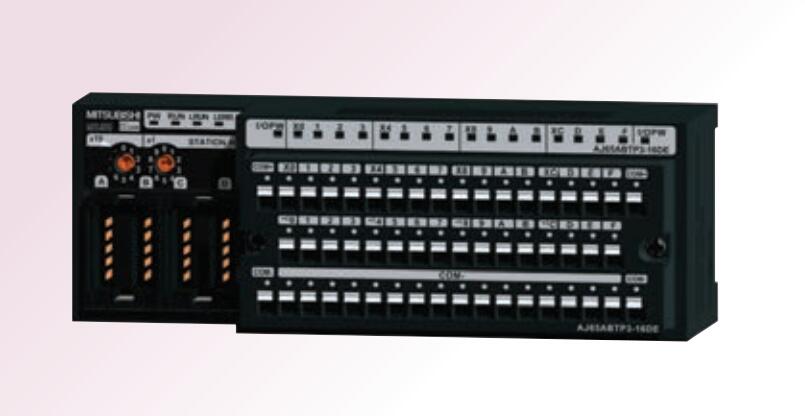
AJ65ABTP3-16DE Market price | AJ65ABTP3-16DE Introduction
- Brand: MITSUBISHI
- Country: JAPAN
- Name: Spring clamping terminal platform push type input module
- Model: AJ65ABTP3-16DE
- Price: 0 >
MITSUBISHI AJ65ABTP3-16DE
SRAM PC card.
Applicable models: A95_GOT (-M3) /A956WGOT. "Output type: transistor output, drain type.
Output points: 32 points.
OFF leakage current: 0.25mA.
Output protection function.
Rated load voltage / current: DC24V/DC24V/0.1A.
External connection: 1 wire.
Fast connector type.
Simple wiring through quick connector.
Can be installed along the 6 direction.
MITSUBISHI PLC program simulation debugging
The basic idea of program simulation debugging is,
In order to facilitate the form of simulation to generate the actual state of the scene,
Create the necessary environmental conditions for the operation of the program AJ65ABTP3-16DE
Depending on the way the field signals are generated,
The simulation debugging has two forms of hardware simulation and software simulation. Drive: MR-H_ACN series SSC-NET compatible AC servo.
Rated output: 15KW.
The servo controller can easily transfer the operation module and the field bus module through the automation interface,
At the same time using different fieldbus modules to achieve different control modes (RS485, RS232, optical fiber, InterBus, ProfiBus),
And the control mode of general inverter is single.
The servo controller is directly connected with a rotary transformer or an encoder, which forms a closed loop of speed and displacement control.
The general inverter can only form an open loop control system.
Servo controller of the control parameters (such as steady-state accuracy and dynamic performance) is better than the general inverter. Temperature sensor: PT100, 3 wire system.
The A1S62RD3 and A1S62RD4 temperature sensor input modules allow the platinum resistance temperature sensing element to be directly connected to the PLC,
This component converts a signal from a temperature measuring element to a numeric value that represents a temperature measurement value,
This temperature value can be used for the control process.
The length of time required to execute the instruction, the length of the user''s program, the type of instruction, and the speed of the CPU execution are very significant,
Generally, a scanning process, the fault diagnosis time,
Communication time, input sampling and output refresh time is less,
The execution time is accounted for the vast majority of.
The response time of PLC is the interval between the time of the change of the external output signal of the PLC and the time of the change of the external output signal which is controlled by it,
Lag time, this is the time constant of the input circuit,
The time constant of the output circuit, the arrangement of the user statement and the use of the instruction,
The cycle scan mode of PLC and the way of PLC to refresh the I/O and so on.
This phenomenon is called the I/O delay time effect.
AJ65ABTP3-16DE Operation manual/Instructions/Model selection sample download link: /searchDownload.html?Search=AJ65ABTP3-16DE&select=5
...more relevant model market price >>>>
Related products
MITSUBISHI
Spring clamping terminal platform push type input module
AJ65ABTP3-16D

Input type: DC input, positive common en
MITSUBISHI
Spring clamping terminal platform push type input module
AJ65ABTP3-16DE

Input type: DC input, negative pulic en
