Brand Sort:
MITSUBISHI
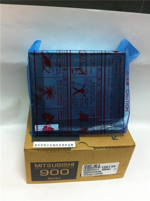
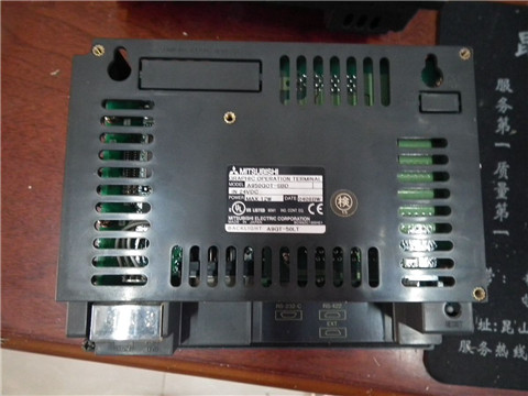
A953GOT-SBD Market price | A953GOT-SBD Introduction
- Brand: MITSUBISHI
- Country: JAPAN
- Name: 6 inch man machine interface
- Model: A953GOT-SBD
- Price: U.S.$ 254.24
MITSUBISHI A953GOT-SBD
Superior high efficiency IPM motor.
Output power: 2.2kw.
Rated speed: 1500r/min.
Voltage level: 200V.
IPM motor MM-EFS series can not be used to run the power frequency power.
The total wiring length of the IPM motor shall not exceed 100m.
1 inverters can not connect multiple IPM motors at the same time. Motor series: low inertia, medium capacity.
Using a serial absolute / incremental encoder.
Rated output power: 5 A953GOT-SBD0kw.
Rated speed: 3000rpm.
With a brake band.
Shaft end: straight shaft.
Performance comparison of servo motor and stepping motor.
Stepper motor as an open-loop control system, and modern digital control technology has the essential link.
In the current domestic digital control system, stepping motor is widely used.
With the emergence of digital AC servo system, AC servo motor is more and more used in digital control system.
In order to adapt to the development trend of digital control, most of the motion control system adopts stepping motor or full digital AC servo motor as executive motor.
Although they are similar in control mode (pulse train and directional signal), there are great differences in performance and application.
The use performance of the two are compared. Applicable models: GT11, HandyGOTRS-232:1, RS-422/485:1.
Transmission speed: 0.3 ~ 19.2kpbs.
Computer connection function.
A3VCPU special.
Printer / peripheral device connection, BASIC language function.
How to choose MITSUBISHI PLC.
MITSUBISHI PLC options include the choice of MITSUBISHI PLC models, capacity, I/O module, power, etc..
MITSUBISHI PLC distribution I/O points and design MITSUBISHI PLC peripheral hardware circuit
Draw the I/O point of the PLC and the input / output device connection diagram or the corresponding table,
This part also can be carried out in second steps.
Design PLC peripheral hardware circuit.
Draw the electrical wiring diagram of the other parts of the system,
Including the main circuit and the control circuit does not enter the PLC, etc..
The electrical schematic diagram of the system composed of I/O PLC connection diagram and PLC peripheral electrical circuit diagram.
So far the system''s hardware electrical circuit has been determined.
A953GOT-SBD Operation manual/Instructions/Model selection sample download link: /searchDownload.html?Search=A953GOT-SBD&select=5
...more relevant model market price >>>>
Related products
MITSUBISHI
6 inch man machine interface
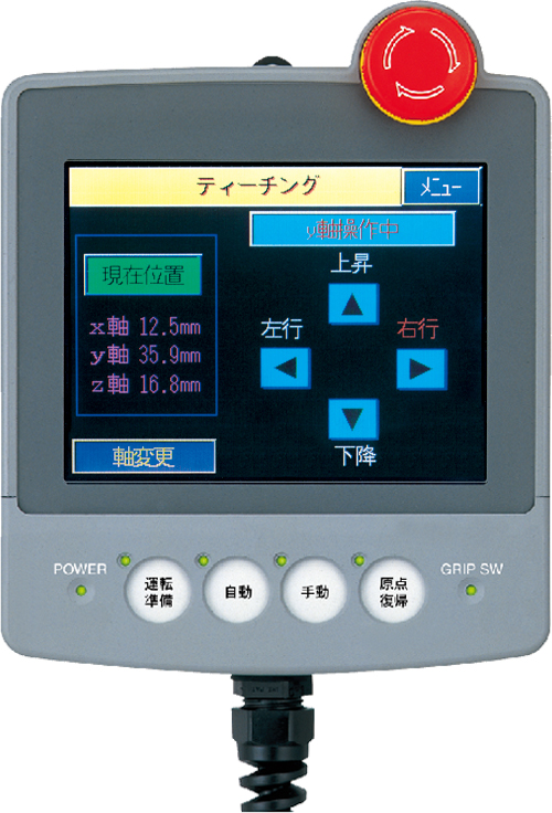
A950GOT-SBD
Series Name: A950GOT.
Size: 6 inches.
Re
MITSUBISHI
6 inch man machine interface
A953GOT-SBD-M3
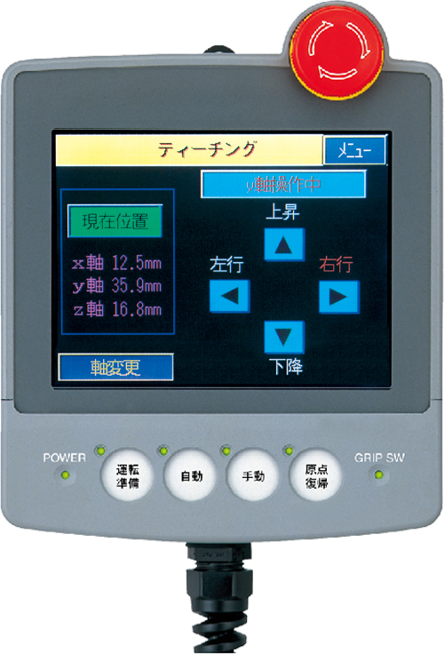
Series Name: A953GOT.
Size: 6 inches.
Re
MITSUBISHI
6 inch man machine interface
A956GOT-SBD
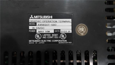
Series Name: A956GOT.
Size: 6 inches.
Re

